 |
 |
||
| Click to view schematic display A | Click to view schematic display B | ||
Process Description
Process Fluid Heating
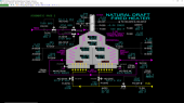
Process fluid from battery limits is fed to both the east pass and the west pass of the natural draft fired heater. The process fluid is first heated in tubes arranged in the convection section using hot flue gases leaving the radiant cells of the fired heater. These hot flue gases combine at the bridgewall which is the section that connects the radiant cells to the convection section. The process fluid is further heated in the east and west radiant cells before leaving the fired heater. The exiting process fluid streams are combined before flowing to the downstream process at battery limits.
Fuel Gas Firing
Fuel gas from battery limits is split into two lines which feed headers serving floor burners arranged on the bottom of the east and west radiant cells. The fuel gas is ignited and burned with combustion air entering from separate plenums serving each radiant cell. A wall divides the radiant cells up to the bottom of the bridgewall. The burned fuel in each cell primarily gives off heat to the process fluid flowing through the coils in the radiant cells via radiation. All the walls of the fired heater and the separating wall in the radiant section are covered with a fireproof lining that reflects heat reaching these walls back to the tubes and coils in the heater. The lining also insulates the heater walls to minimize heat loss to ambient.
Stack Effect, Flue Gas Flow and Draft
The hot flue gases rise through the radiant cells, combine in the bridgewall, flow up through the convection section and then rise up the stack on top of the fired heater. Even though the flue gas cools significantly as it passes up through the convection section, it is hot enough at the top of the convection section to so that the density of the flue gas is significantly lower than the density of the ambient air surrounding the heater. This density difference causes the hot flue gas to rise up the stack and is commonly known as the ‘stack effect’. It is the same principle that makes a hot-air balloon rise.
A large damper installed at the base of the stack permits adjustment of the flow rate of flue gas up the stack. To avoid complete blockage of flue gas flow when the damper is in the fully closed position, about 10% of the cross-sectional area of the damper is cut out. This prevents overpressuring of the fired heater.
The flow of flue gas up the stack due to the stack effect induces a slightly negative pressure difference from ambient at the bottom of the stack. This negative pressure difference is known as draft. Draft is higher (i.e. the pressure is more negative) as the flue gas temperature increases. Therefore, flue gas draft is normally highest in the radiant section, decreases at the bridgewall and is lowest at the top of the convection section. \
Combustion Air
The negative pressure conditions of the radiant cells provide the driving force to pull ambient air from the air plenums into the radiant cells through air registers in the floor burners. Combustion air from ambient enters the east and west air plenums through large dampers and is drawn in through the air registers on each burner.The air dampers control the flow rates of combustion air into the plenums and through the air registers on the burners.
Product Specifications
Approximately 7,500 BPD of process fluid is heated from 68 DEG F to 1,200 DEG F in the natural draft fired heater. The process fluid is split equally between the east pass and the west pass of the furnace.
1,597 SCFM of fuel is required to accomplish this task. The fuel is split equally between the east burners and the west burners.
At design conditions, the furnace and the stack has been designed to provide sufficient draft to provide 125% excess air to the furnace with both the air registers and the stack damper at 50% open.
Radiant box temperatures are 2,132 DEG F, bridge wall temperature is 1,608 DEG F, and the average stack temperature is 500 DEG F. Crossover temperatures of the process fluid 445 DEG F.
The resulting draft in the furnace is -0.27 INH2O in the radiant sections, -0.15 INH2O at the bridge wall, and -0.061 INH2O in the stack.
Overview
The furnace has been designed with sufficient capacity to heat process fluid to design specifications at approximately twice the design flow rate.
Control Valves
All control valves in the system have linear flow characteristics.
Instrumentation
Process-side Instrumentation
The process feed flow is controlled by flow controller FIC-101. FIC-101 also serves as a trip instrument (see Logic System section below). Flow to the east and west passes can be adjusted by varying the positions of valves HIC-101E and HIC-102W respectively. Process inlet temperature is indicated by TI-101. Process outlet temperature is controlled by TIC-102 which modulates fuel flow to the burners. East and west pass outlet temperatures are indicated by TI-102E and TI-102W respectively. East and west pass crossover temperatures are indicated by TI-101E and TI-101W respectively.
Fuel Gas Instrumentation
Fuel flow to the burners is controlled by temperature controller TIC-102 which is cascaded to fuel flow controller FIC-201. Fuel flow to the east and west burners can be adjusted by varying the positions of valves HIC-201E and HIC-201W respectively. Fuel inlet temperature is indicated by TI-201.
Flue Gas Instrumentation
Temperatures in the east and west radiant cells of the furnace are indicated by TI-301E and TI-301W respectively. Bridge wall temperature is indicated by TI-302. Stack inlet and outlet temperatures are indicated by TI-303 and TI-304 respectively.
The draft in the east and west radiant sections of the furnace is indicated by PI-301E and PI-301W respectively.Bridge wall draft is indicated by PIC-302. Stack draft is indicated by PI-303.
The stack damper position is controlled by HIC-301.
Volume percent oxygen in the stack gas is indicated by AIC-301.
The oxygen concentrations (volume %) of the flue gas in the east and west cells are indicated on AI-302E and AI-302W, respectively. The carbon monoxide concentrations (PPM) of the flue gas in east and west cells are indicated on AI-303E and AI-303W, respectively. The combustibles/hydrocarbon concentration (PPM) of the flue gas in east and west cells are indicated on AI-304E and AI-304W, respectively. The CO analyzers and the combustibles analyzers also serve as trip instruments.
Combustion Air Instrumentation
Air flows into the plenums serving the east and west burners can be trimmed by varying the positions of the respective air dampers HIC-301E and HIC-301W.
The ambient air temperature and pressure is indicated by TI-300 and PI-300 respectively.
The BURNER-E and BURNER-W switches act as both igniters and flame indicators.
Note: These switches are not identified by tag on the main process schematic but are accessible on the simulator just above their respective burner assembly.
Advanced Controls
The draft in the furnace is controlled by bridge wall pressure controller PIC-302. The output of PIC-302 is cascaded to the setpoint of stack damper position controller HIC-301. Adjusting the stack damper position changes the flow of flue gas up the stack which, in turn, affects the draft in the fired heater. Normally, HIC-301 is in cascade mode and PIC-302 is in automatic mode.
The output of stack O2 controller AIC-301 is cascaded to the setpoints of both combustion air damper controllers HIC-301E and HIC-301W. If desired, differences between the east and west air flows are made by adjusting the ratio setting of HIC-301E or HIC-301W. Normally, HIC-301E and HIC-301W are in cascade mode and AIC-302 is in automatic mode.
Logic System
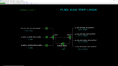
The following conditions will cause a trip of the fired heater:
- FIC-101 PROCESS FLOW is in the low alarm state (below 4,500 BPD)
- AI-304E HC EAST RAD CELL is in the high alarm state (above 500 PPM)
- AI-304W HC WEST RAD CELL is in the high alarm state (above 500 PPM)
The following actions occur on a trip:
- XA-301 HEATER TRIP will alarm
- FIC-201 FUEL TOTAL is locked in Manual Mode and 0% output
- HIC-301 STACK DAMPER is locked in Manual Mode and 100% output
- HIC-301W REGISTER WEST is locked in Manual Mode and 100% output
- HIC-301E REGISTER EAST is locked in Manual Mode and 100% output
- XI-301PD PURGE TIMER will count down from 60 seconds
While the purge timer is counting down to zero, none of the trip-affected controllers can be operated, even if the process trip conditions will not cause a trip. This ensures enough time is given to purge the fired heater with air before restarting.
After all process trip conditions are in a good condition and the fired heater has been sufficiently purged with air, the READY indicator on the trip logic schematic will indicate that the fired heater can be restarted.