 |
 |
||
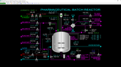
| Click to view schematic display A | Click to view schematic display B |
Process Description
The purpose of the Pharmaceutical Batch Reactor is to react two aqueous feeds to completion. The simulated feeds are a strong acid and a weak organic base. The reaction that takes place is the neutralization of the organic base by the addition of the strong acid.
Batch reactors are the workhorse of the pharmaceutical, foods and fine chemicals industries. They are also important in the growing bio-fuels industry. Operators of these reactors must precisely follow recipes and operating procedures to ensure a high quality product is obtained. Failure to do so often results in dumping of the batch, delayed production schedules and loss of profit to the operating company.
Major Equipment
The Pharmaceutical Batch Reactor process consists of the following major equipment:
- Jacketed Batch Reactor, R-101
- Reactor Condenser, E-101
- Reactor Pump, P-101
- Product Receiver, D-201
- Catch Tank, T-101
- Product Pump, P-201
Process Overview: Batch Reactor
The Batch Reactor R-101 is fed by a header which receives the following liquids from battery limits:
- A solution containing reactant “A”
- A solution containing reactant “B”
- Solvent “A”
- Solvent “B”
- Water
The header also receives recirculating reactor liquid from Reactor Pump P-101. These liquids are charged to the top of Batch Reactor R-101. The water is used for washing the Batch Reactor after a batch of reactants is processed in R-101. The solvents are used to dissolve any solids that may have accumulated in the system, if needed.
The solutions containing reactants will result in a reaction within R-101. The reactor contents are mixed with a motor-driven agitator consisting of paddles attached to the shaft of the agitator. A series of specially designed baffles on the inside walls of the reactor improve the mixing of the contents of the reactor, as well as maximize heat transfer with the circulating water in the exterior jacket.
The outside of Batch Reactor R-101 is jacketed to allow cooling water or hot water to circulate against the wall of R-101. Cooling water is used for temperature control when the reaction releases heat. When the reaction absorbs heat, hot water is circulated. Water exiting the jacket is returned to battery limits.
Nitrogen is provided to the top of R-101 to purge the vapor space. Nitrogen, purged vapors and any vapors flashing from the liquid in the reactor are routed to the Reactor Condenser E-101. The shell side of E-101 can be routed to the atmospheric vent system or the vacuum system. E-101 is cooled using cooling water.
Any condensate from E-101 can be drawn off to battery limits or it can be returned to R-101.
The bottom outlet of the Batch Reactor R-101 feeds Reactor Pump P-101. P-101 is a motor-driven centrifugal pump that is used to recirculate the reactor contents to the top of the reactor and to pump the finished reactor contents to the Product Receiver D-201. Recirculating the reactor’s contents eliminates settling of reactants at the bottom of the reactor and improves mixing of the reactants.
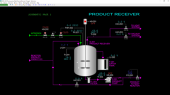
Product Receiver
Product Receiver D-201 is a vessel of identical size to Batch Reactor R-101 that is used to store the finished product from R-101. It is also similarly configured to R-101 in the following ways:
- It has a nitrogen purge line
- It has an atmospheric vent line
- It has a vacuum connection
- It has a motor-driven agitator
- It has a pump for recirculating liquid to the reactor and to deliver product to another reactor
Feed from Reactor Pump P-101 and recirculated liquid from Product Pump P-201 is routed to the top of D-201.
Like Reactor Pump P-101, Product Pump P-201 is a motor-driven centrifugal pump.
In the event of over-filling the Product Receiver, Catch Tank T-201 will receive any liquid that spills over from D-201.
Equipment Specifications
Batch Reactor
Batch Reactor R-101 is a stainless-steel vessel with a gross volume of 1,000 gallons. The maximum usable capacity is roughly 80% of the gross volume. The vessel is lined on the inside to prevent corrosion by acids or bases.
Cooling water is supplied to the jacket of the reactor at 77 DEG F in cooling mode and hot water is supplied at 185 DEG F in heating mode. The cooling/heating mode is selectable and depends on whether the reaction gives off or takes in heat. \
Reactant A is aqueous hydrochloric acid at a concentration of 30 weight %. Reactant B is an aqueous solution of a weak organic base at a concentration of 79 weight %. At these concentrations, the neutralization ratio of the solutions is approximately 0.57 volume of hydrochloric acid per volume of organic base. The reaction gives off 57.7 KJ/mol of heat.
The neutralization reaction occurs very quickly and is only limited by the degree of mixing of the two reactants. Agitation and maximum reactor recycle flow ensure the reaction occurs completely in a very short time within the reactor.
The neutralized organic base is heat sensitive and should not be exposed to temperatures higher than 100 DEG F. In practice, it is desirable to operate the reactor with a maximum temperature approximately 10 degrees below this limit. Considering the large amount of heat that is given off by the neutralization reaction, it is necessary to first charge the reactor with the organic base and then add acid at a relatively slow rate so as not to exceed the heat removal capacity of the jacket. This approach allows keeping the reactor contents from getting too warm and exceeding the temperature limits given above. It typically takes about one hour to neutralize a full batch of organic feed once acid addition has started.
The reactor contents are mixed with a motor-driven agitator consisting of paddles attached to the shaft of the agitator. A series of specially designed baffles on the inside walls of the reactor improve the mixing of the contents of the reactor, as well as maximize heat transfer with the circulating water in the exterior jacket.
After complete neutralization of the organic base solution, the neutralized organic product will have a concentration of 54.4 weight %. The solution of a perfectly neutralized product will have a pH of 6.5.
R-101 Cleaning
Two solvents and water are available for cleaning the Batch Reactor. Solvent A is hexane and solvent B is benzene. Solvents are normally used to dissolve accumulated solids and gums from the reactor and its associated equipment and piping. Although solids and gums are not simulated, the procedures for using solvents to clean the reactor can be practiced on the simulator if desired.
Cleaning the Batch Reactor with water is a normal operation after a product has been prepared.
Batch Reactor Protective Systems
The reactor has two protective systems to keep it from being overfilled with liquids or over pressured with nitrogen. Solenoid operated valves will close off feed or nitrogen upon receiving a signal indicating a dangerous condition exists. These solenoid valves must be manually reset after the dangerous condition has cleared.
The Batch Reactor also has a nitrogen line for purging the vessel or for providing an inert environment.
Reactor Pump P-101
Reactor Pump P-101 is a motor-driven, centrifugal pump. Its design capacity is 45 GPM with a head of 30 PSIG.
The Reactor Pump has two purposes:
- to recirculate reactants from the bottom of the Reactor back to the inlet
- to pump the product from the reactor to the product receiver
Condenser E-101
Condenser E-101 uses cooling water to cool and condense any vapors generated in the Batch Reactor R-101. The condenser can be vented to atmosphere via the vent system. It can also be lined up to the vacuum system if desired.
Any liquid leaving can be routed back to the Batch Reactor R-101 or can be taken off to battery limits if desired. The normal lineup is to return any liquid from the condenser back to the reactor. During the typical conditions of the neutralization reaction there is no condensate generated in E-101.
Product Receiver D-201
The Product Receiver D-201 is the same size as the Batch Reactor R-101. It is used to hold the neutralized product from R-101 for feed to another reactor. The Product Receiver provides production scheduling flexibility because another batch of product can be prepared in the Batch Reactor while product is being fed to another reactor from the Product Receiver.
D-201 is also similarly configured to R-101 in the following ways:
- It has a nitrogen purge line
- It has an atmospheric vent line
- It has a vacuum connection
- It has a motor-driven agitator
- It has a pump for recirculating liquid to the reactor and to deliver product to another reactor
Feed from Reactor Pump P-101 and recirculated liquid from Product Pump P-201 is routed to the top of D-201.
A solenoid operated valve on the nitrogen line will close in case the pressure of D-201 becomes too high.
Product Pump P-201
Product Pump P-201 is a motor-driven centrifugal pump and is identical to Reactor Pump P-101.
Catch Tank T-201
In the event of over-filling the Product Receiver, Catch Tank T-201 will receive any liquid that spills over from D-201.
Instrumentation
Batch Reactor
FIC-101 controls the flow of solvent A (hexane) to R-101 by adjusting the opening of the solvent A valve FV-101.
FIC-102 controls the flow of solvent B (benzene) to R-101 by adjusting the opening of the solvent B valve FV-102.
FIC-103 controls the flow of reactant A (hydrochloric acid solution) to R-101 by adjusting the opening of the reactant A valve FV-103.
FIC-104 controls the flow of reactant B (organic base) to R-101 by adjusting the opening of the reactant B valve FV-104.
FIC-105 controls the flow of water to R-101 by adjusting the opening of the water valve FV-105.
TIC-103 controls either the flow of cooling water (when jacket mode switch HS-103 is in the COOL position) or the flow of hot water (when HS-103 is in the HEAT position). Note the relationship between TIC-103 output and the cooling water supply valve position is direct (0% = closed) while the relationship between TIC-103 output and the hot water supply valve is reversed (0% = open). This is important when switching between modes. However, TIC-103 will function correctly in either mode.
When HS-103 is in the COOL position, the hot water supply valve is closed. When HS-103 is in the HEAT position, the cooling water supply valve is closed.
Switch HS-102 opens and closes the nitrogen supply block valve HV-102.
Switch XV-102 resets (opens) or trips (closes) the solenoid valve XV-102 on the nitrogen supply line. Switch XV-102 can be accessed by clicking on the solenoid of XV-102 of Schematic 2.
Switch XV-101 resets (opens) or trips (closes) the solenoid valve XV-101 on the reactor feed line. Switch XV-101 can be accessed by clicking on the solenoid of XV-101 of Schematic 2.
Switch HS-101 operates the motor of the agitator of R-101.
HIC-102 adjusts the flow of cooling water through E-101.
HIC-103 adjusts the valve opening on the line from E-101 to the atmospheric vent system.
HIC-104 is used to apply vacuum to E-101 and R-101.
Switch HS-105 aligns the condensate from E-101 to either R-101 or to battery limit.
Switch HS-104 operates the motor of Reactor Pump P-101.
HIC-101 adjusts the valve position of HV-101 which recycles reactor liquid back to the feed header.
FIC-106 controls the flow of liquid from P-101 through valve FV-106 and to the Product Receiver D-201.
LI-101 indicates the liquid level in R-101. LAH-102 indicates the same and trips the solenoid on XV-101 at 90% level to close off any liquid feeding R-101.
PI-101 indicates the pressure inside R-101. PAH-102 indicates the same and trips the solenoid on XV-102 at 10.0 PSIG to close off nitrogen to R-101.
AI-102A indicates the weight % of HCl in R-101 (reactant A).
AI-101B indicates the weight % of organic base in R-101 (reactant B)
AI-101C indicates the weight % of neutralized organic in R-101.
AI-103 indicates the pH of liquid in R-101.
Note that the analyzers will read zero when there is no liquid in R-101. Also, AI-103 will indicate zero if no water is present in R-101 (e.g. when using only solvent A or B in R-101).
While not shown on Schematic 2, the following analyzers are presented on operating group 6:
AI-101A indicates the weight % of HCl in feed reactant A.
AI-101B indicates the weight % of organic base in feed reactant B.
Product Receiver
Switch HS-202 opens and closes the nitrogen supply block valve HV-202.
Switch XV-202 resets (opens) or trips (closes) the solenoid valve XV-202 on the nitrogen supply line. Switch XV-202 can be accessed by clicking on the solenoid of XV-202 of Schematic 3.
Switch HS-201 operates the motor of the agitator of D-201.
HIC-202 adjusts the valve opening on the line from D-201 to the atmospheric vent system.
HIC-203 is used to apply vacuum to D-201.
Switch HS-203 operates the motor of Product Pump P-201.
HIC-201 adjusts the valve position of HV-201 which recycles liquid from D-201/P-201 back to the feed header.
FIC-201 controls the flow of liquid from P-201 through valve FV-201 and to the next reactor.
LI-201 indicates the liquid level in D-201.
PI-201 indicates the pressure inside D-201. PAH-202 indicates the same and trips the solenoid on XV-202 at 10.0 PSIG to close off nitrogen to D-201.
Interlocks
There are two protective interlock systems for the Batch Reactor R-101 as follows:
- PAH-102 trips solenoid operated valve XV-102 to the closed position on high pressure (10 PSIG).
- LAH-102 trips the solenoid operated valve XV-101 on high reactor liquid level (90%).
There is one protective interlock system for the Product Receiver D-201 as follows:
- PAH-202 trips solenoid operated valve XV-202 to the closed position on high pressure (10 PSIG).