 |
 |
||
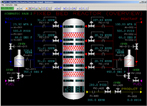
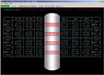
| Click to view schematic display A | Click to view schematic display B |
Process Description
The SPM-2300 Fixed Bed Reactor Process Simulation can be configured to react any two gases. The reaction can be exothermic or endothermic. The default configuration catalytically reacts ethylene (reactant A) with benzene (reactant B), an exothermic reaction, to produce ethylbenzene (product C), an intermediate chemical used in the manufacture of styrene monomer. There are no side or competing reactions simulated.
Reactants A and B are fed to each of the four fixed beds through fired heaters where their temperatures are raised to the optimum reaction temperature. Reactant A temperature is maintained substantially lower than reactant B so as to allow for inter-bed quenching, a technique used to control reactor bed temperatures.
Reactant A feedstock is assumed to come from a typical refinery FCC. Consequently, there is a substantial concentration of inerts in the feed. Since the reaction is highly exothermic, the inerts serve to dilute the feed and aid in preventing a reactor run-away.
Reactant B feedstock is assumed to be of the highest available industrial grade and is therefore effectively 100% pure for the purposes of this simulation.
The reactor beds are sized to convert all of reactant A to product. The inlet molar ratio of reactant B to reactant A is maintained at ten to one for each bed. Since the flow of reactant A to each bed is maintained the same, the vast majority of reactant B must be fed to the first bed with only a small make-up of reactant B being fed to subsequent beds.
The product stream is purified downstream of the reactor through a series of distillation columns. The inerts are vented, recompressed, and used as a fuel gas elsewhere in the plant. Reactant B is recovered, purified, and recycled back to the reactor. The purification of the product stream is outside the scope of this simulation.
Instrumentation
The reactant A feed flow loop is outfitted with a composition analyzer (AI-001) that measures weight percent A, the balance being inerts. The supply temperature and pressure are indicated by TI-001 and PI-001 respectively. The feed block valve can be opened and closed with switch HV-001. Total reactant A flow is indicated by FI-011.
Reactant A is heated to reaction temperature by a fired heater. Temperature controller TIC-011 controls reactant A feed temperature by modulating the fuel gas flow to the fired heater. The fuel gas block valve can be opened and closed with switch HV-001.
Reactant A flow to each of the four catalytic reactor beds is modulated by flow controllers FIC-111, FIC-211, FIC-311, and FIC-411 respectively.
The reactant B feed flow loop is outfitted with a composition analyzer (AI-002) that measures weight percent B, the balance being inerts. The supply temperature and pressure are indicated by TI-002 and PI-002 respectively. The feed block valve can be opened and closed with switch HV-002. Total reactant B flow is indicated by FI-012.
Reactant B is heated to reaction temperature by a fired heater. Temperature controller TIC-012 controls reactant B feed temperature by modulating the fuel gas flow to the fired heater. The fuel gas block valve can be opened and closed with switch HV-002.
Reactant B flow to each of the four catalytic reactor beds is modulated by flow controllers FIC-112, FIC-212, FIC-312, and FIC-412 respectively.
Inlet bed temperatures are indicated by TIC-110, TIC-210, TIC-310, and TIC-410 respectively. Outlet bed temperatures are indicated by TIC-120, TIC-220, TIC-320, and TIC-420 respectively.
The pressure over each bed is indicated by PI-110, PI-210, PI-310, and PI-410 respectively. Reactor pressure is controlled by PIC-420 which modulates the reactor effluent flow, indicated by FI-400. The reactor effluent block valve can be opened and closed with switch HV-420. Product discharge pressure is indicated by PI-003.
Total mass flow entering each reactor bed is indicated by FI-110, FI-210, FI-310, and FI-410 respectively. Total mass flow leaving each reactor bed is indicated by FI-120, FI-220, FI-320, and FI-420 respectively.
Reactant A bed inlet compositions are indicated by AI-111, AI-211, AI-311, and AI-411 respectively. Reactant B bed inlet compositions are indicated by AI-112, AI-212, AI-312, and AI-412 respectively. Product C bed inlet compositions are indicated by AI-113, AI-213, AI-313, and AI-413 respectively. Inerts bed inlet compositions can be determined by difference.
Reactant A bed outlet compositions are indicated by AI-121, AI-221, AI-321, and AI-421 respectively. Reactant B bed outlet compositions are indicated by AI-122, AI-222, AI-322, and AI-422 respectively. Product C bed outlet compositions are indicated by AI-123, AI-223, AI-323, and AI-423 respectively. Inerts bed outlet compositions can be determined by difference.