Process Description
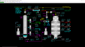
The Atmospheric Distillation Unit (ADU) separates crude oil from tankage into lighter end products such as gas, gasoline, naphtha, kerosene, and gas oil to be used as motor fuels, heating fuels and chemical feedstocks by distillation at near-atmospheric pressure. The remainder of the crude oil that is not separated in the ADU is collected in the bottom of the Atmospheric Distillation Tower and is referred to as atmospheric residue. The atmospheric residue is then sent to the Vacuum Distillation Unit (VDU) for additional distillation under deep vacuum conditions.
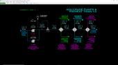
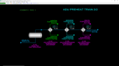
Crude Oil Pumping & Preheating
Crude oil from storage is pumped by Crude Charge Pumps, P-100/P-100B, which are electric motor-driven centrifugal pumps and sent through a series of three heat exchangers E-101, E-102 and E-103 to recover heat from ADU products being sent to storage. E-101 is the ADU Feed/Naphtha Product Exchanger, E-102 is the ADU Feed/Kerosene Product Exchanger and E-103 is the ADU Feed/Gas Oil Product Exchanger. The Crude oil from tankage is normally at 100 DEG F and is preheated to 205.4 DEG F by the time it exits E-103. The crude oil is sent to Desalter, D-100.
Preheated crude oil from E-103 is sent through Desalter, D-100, for water washing to remove salt and other water-soluble impurities in the crude oil. The Desalter is not simulated in detail, but it is possible to carryover washwater into the crude oil. Crude oil from D-100 flows to another series of three heat exchangers E-104, E-105 and E-106 to recover heat from ADU Tower, T-100, pumparound circuits that provide circulating reflux for separation of the crude oil into products. E-104 is the ADU Feed/Naphtha Pumparound Exchanger, E-105 is the ADU Feed/Kerosene Pumparound Exchanger and E-106 is the ADU Feed/Gas Oil Pumparound Exchanger. The Crude oil is preheated to 269.7 DEG F by the time it exits E-106. In the design operating condition, no heat is obtained from E-105 and E-106 because the corresponding pumparound systems are out of service. The crude oil from E-106 is sent to ADU Furnace, F-100.
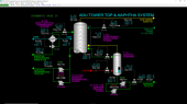
Atmospheric Distillation Tower
The Atmospheric Distillation Tower, T-100, contains 20 fractionation trays, is equipped with the pumparound circuits, an overhead reflux system, and three side strippers (for naphtha, kerosene, and gas oil products).
The liquid from the Atmospheric Furnace enters the tower bottom, where it is collected and sent for further processing to the Vacuum Distillation Unit (VDU) along with any excess distillate produced from the gas oil section of the tower. Steam is injected into the base of the tower and in the three side strippers to reduce the hydrocarbon partial pressure by stripping some light boiling components from the bottoms liquid. The vapors from the Atmospheric Furnace, F-100, enter the tower below tray 20.
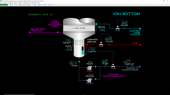
ADU Bottom
Partially vaporized crude oil enters T-100 and separates into liquid and vapor. The liquid falls into the bottom of T-100 and combines with liquid falling from tray 20. The bottoms product is very heavy (i.e. has a high molecular weight) and is pumped to the VDU Furnace, F-200, by ADU Bottoms Pumps, P-114/P-114B, which are electric motor-driven centrifugal pumps.
Bottoms stripping stream combines with the vaporized portion of the crude feed and enters tray 20. Trays 19 and 20 are considered the flash zone of T-100. Excess vaporized feed, which is condensed in the upper sections of T-100, flows back down to the flash zone from the Gas Oil draw tray (tray 18). This excess liquid is commonly referred to as overflash and washes any entrained liquid from F-100 down to the bottom of T-100. Without significant overflash liquid returned to the flash zone, the gas oil product taken from tray 18 can be contaminated with non-distillate (i.e. heavy) components.
Gas Oil System
At tray 18, a partial draw pan is located from which gas oil product is drawn. The gas oil product flows by gravity to the top of the Gas Oil Stripper, T-113. Stripping steam is used to remove the light ends, improving the flash point. The stripped gas oil product is pumped to storage by Gas Oil Product Pumps, P-113/P-113B, which are electric motor-driven centrifugal pumps. The product gas oil is cooled by crude oil feed in E-103 before being routed to storage.
Excess gas oil from tray 18 flows down to the flash zone to wash any entrained liquid from F-100 to the bottom of T-100.
Circulating gas oil reflux (pumparound) is provided by Gas Oil Pumparound Pumps, P-117/P-117B, which are electric motor-driven centrifugal pumps. Circulating gas oil from tray 18 is pumped to E-106 to be cooled by crude oil feed. Cooled circulating gas oil is returned to tray 13. Normally, the Gas Oil Pumparound system is out of service at the design condition. The system has been added to the original design of the Atmospheric Distillation Unit (ADU) to help process lighter crude feeds more efficiently.
Kerosene System
At tray 12, a partial draw pan is located from which kerosene product is drawn. The kerosene product flows by gravity to the top of the Kerosene Stripper, T-112. Stripping steam is used to remove the light ends, improving the flash point. The stripped gas oil product is pumped to storage by Kerosene Product Pumps, P-112/P-112B, which are electric motor-driven centrifugal pumps. The product kerosene is cooled by crude oil feed in E-102 before being routed to storage.
Excess kerosene from tray 12 flows down to the gas oil section (trays 13 through 18). Drawing less kerosene to T-112 will result in sending more kerosene to the gas oil system, thereby making the product gas oil lighter (i.e. lower molecular weight).
Circulating gas oil reflux (pumparound) is provided by Kerosene Pumparound Pumps, P-116/P-116B, which are electric motor-driven centrifugal pumps. Circulating kerosene from tray 12 is pumped to E-105 to be cooled by crude oil feed. Cooled circulating kerosene is returned to tray 7. Normally, the Kerosene Pumparound system is out of service at the design condition. The system has been added to the original design of the Atmospheric Distillation Unit (ADU) to help process lighter crude feeds more efficiently.
Naphtha System The last product side draw is located at tray 6, where the naphtha product is drawn. The naphtha product flows by gravity to the top of the Naphtha Stripper, T-111. Stripping steam is used to remove the light ends, improving the flash point. The stripped naphtha product is pumped to storage. Naphtha pumparound is drawn from tray 6 and pumped by Naphtha Pumparound Pumps, P-115/P-115B, which are electric motor-driven centrifugal pumps. Circulating naphtha is sent to E-104 to be cooled by crude oil feed. Cooled naphtha from E-104 returns to the Naphtha Pumparound Cooler, E-115, and is cooled further by cooling water. The cooled naphtha stream is returned to tray 2. This pumparound stream normally generates all of the internal reflux for the Atmospheric Distillation Tower, T-100, which promotes separation of the vapor from the Atmospheric Furnace, F-100, into the various hydrocarbon products drawn from T-100. In alternate operating conditions, the Kerosene and Gas Oil Pumparound systems can be used to provide a large portion of this internal reflux. This approach gives more flexibility in meeting quality specifications for the kerosene and gas oil products.
Overhead System
Vapor from the top tray of the Atmospheric Distillation Tower, T-100, is routed to Overhead Condenser, E-110, which uses cooling water to condense most of the hydrocarbons (light gasoline) and steam from the vapor. The condensed gasoline and sour water (containing hydrogen sulfide and ammonia) are separated by gravity in the Reflux Drum, D-111. Collected gasoline from D-111 is pumped to the top of T-100 as top reflux and to storage by Overhead Pumps, P-110/P-110B, which are electric motor-driven centrifugal pumps. The sour water produced from E-110 is collected in the boot of D-111 and is pumped by Sour Water Pumps, P-120/P-120B, which are electric motor-driven centrifugal pumps to a storage tank outside battery limits for subsequent treating to remove dissolved ammonia and hydrogen sulfide before disposal.
The vapor separated in the Reflux Drum, D-111, is compressed in Gas Compressor, K-130, which is an electric motor-driven reciprocating compressor, and on sent to a fuel gas treater outside battery limits for sulfur removal prior to being used as a utility fuel gas. Any recycled gas from K-130 is sent back to the Overhead Condenser, E-110, to be cooled.
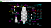
VDU Process Flow
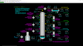
The VDU (Vacuum Distillation Unit) separates residue from the ADU (Atmospheric Distillation Unit) into light vacuum gas oil (LVGO), heavy vacuum gas oil (HVGO), slop wax, and vacuum residue using distillation under vacuum conditions. The hot feed from the ADU is heated even higher in the VDU Furnace to vaporize most of the heavier components. The vaporized components in the feed are condensed in the VDU by three circulating refluxes and removed as products. Sour gas, light slop oil and sour water are produced in the overhead vacuum system.
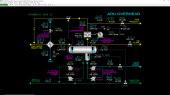
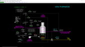
VDU Furnace
Feed from P-114/P-114B is partially vaporized in the Vacuum Furnace, F-200, using fuel gas. Normally, the feed is heated to 750 DEG F. The heated crude is sent to the bottom section of the Vacuum Distillation Tower, T-200, where it is separated into slop oil, light vacuum gas oil (LVGO), heavy vacuum gas oil (HVGO), slop wax, and bottoms vacuum residue.
Combustion air is provided to F-200 by Forced Draft Fan, K-202. F-200 is outfitted with an ignition system to perform an initial light off of the fuel gas during startup. The furnace draft and oxygen are assumed to be ideally regulated in F-200. An interlock system stops fuel gas in the event of low crude flow rate, loss of K-202 or loss of flame detection in F-200.
Vacuum Distillation Tower
The Vacuum Distillation Tower consists of 4 packed sections above the feed nozzle and a trayed stripping section below the feed nozzle. It is equipped with three side draws and pumparound sections for LVGO, HVGO, and slop wax products. The tower consists of variable cross-section areas to produce optimal gas velocities for good liquid-vapor contacting with a minimal pressure drop. Vacuum towers are typically designed this way because vacuum conditions result in low gas densities which, in turn, would result in high velocities in a conventional distillation tower.
Stripping Section
The liquid from the Vacuum Furnace, F-200, and excess wash oil from the flash zone above the feed nozzle into are collected and routed to the stripping section of Vacuum Distillation Tower, T-200. This combined liquid (vacuum residue) flows into the stripper section before being collected in the tower bottom, where it is collected and sent for further processing, typically in a Delayed Coker Unit. Steam is injected below the bottom tray of the stripping section to reduce the hydrocarbon partial pressure by stripping some light boiling components from the bottoms liquid. The steam also serves to cool the residue to minimize cracking and coking of the vacuum residue. The vapors from the Vacuum Furnace are routed to the flash zone of the tower along with vapors produced by the stripping section.
Vacuum residue from the stripping section is collected in the bottom of T-200 and pumped to battery limits by VDU Bottoms Pumps, P-214/P-214B, which are electric motor-driven centrifugal pumps.
Flash Zone
The flash zone serves partially quench the hot vapor from the Vacuum Furnace and to wash down heavy residue droplets that are entrained with the vapor. A portion of the circulating slop wax is used as the wash oil. Without the flash zone, these entrained droplets would pollute the circulating slop wax distillate and degrade its quality. The flow rate of wash oil needs to be sufficiently high at all times to ensure the packing of the flash zone is completely wetted. At low wash oil rates most of the wash oil will be vaporized by the hot vapor from the Vacuum Furnace leading to insufficient distribution of wash oil on the packing.
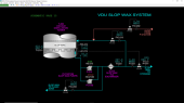
Slop Wax Section
The slop wax pan is located at the base of the slop wax packed section. The pan collects liquid from the packing of the slop wax section. Vapors from the flash zone flow through risers in the pan and up into the packing of the slop wax section. The vapor risers are capped to prevent slop wax liquid from falling through risers. Product, pumparound slop wax and wash oil for the flash zone are pumped from the slop wax pan by Slop Wax Pumps, P-213/P-213B, which are electric motor-driven centrifugal pumps.
The slop wax product and pumparound from P-213/P-213B are cooled in Slop Wax P/A Exchanger, E-213. The cooling stream of E-213 is assumed to be a cool thermal oil stream used for heating service outside the Vacuum Distillation Unit (VDU). Some of the cooled slop wax product is sent to storage while the pumparound stream is returned to the tower at the top of the slop wax section packing. Uncooled slop wax for wash oil is taken off upstream of E-213.
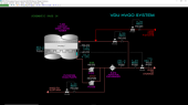
HVGO Section
The Heavy vacuum gas oil (HVGO) pan is located at the base of the HVGO packed section. The pan collects liquid from the packing of the HVGO section. Vapors from the slop wax section flow through risers in the pan and up into the packing of the slop wax section. The vapor risers are capped to prevent slop wax liquid from falling through risers. Product, pumparound HVGO and reflux for the slop wax section are pumped from the HVGO pan by HVGO Pumps, P-212/P-212B, which are electric motor-driven centrifugal pumps.
The HVGO product and pumparound from P-212/P-212B are cooled in HVGO P/A Exchanger, E-212. The cooling stream of E-212 is assumed to be a cool thermal oil stream used for heating service outside the VDU. Some of the cooled HVGO product is sent to storage while the pumparound stream is returned to the tower at the top of the HVGO section packing. Uncooled HVGO for pumpdown to the slop wax section is taken off upstream of E-212. There is normally no HVGO reflux sent to the slop wax section, but this line can be used to adjust product properties of the slop wax product if needed.
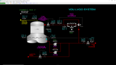
LVGO Section
The Light Vacuum Gas Oil (LVGO) pan is located at the base of the LVGO packed section. The pan collects liquid from the packing of the LVGO section. Vapors from the HVGO section flow through risers in the pan and up into the packing of the slop wax section. The vapor risers are capped to prevent slop wax liquid from falling through risers. Product, pumparound LVGO and reflux for the HVGO section are pumped from the LVGO pan by LVGO Pumps, P-211/P-211B, which are electric motor-driven centrifugal pumps.
The LVGO product and reflux for the HVGO section are taken directly from P-212/P-212B. The pumparound stream from P-212/P-212B is cooled in LVGO Air Cooler, E-211, and is returned to the tower at the top of the LVGO section packing. There is normally no LVGO reflux sent to the HVGO section, but this line can be used to adjust product properties of the HVGO product if needed.
Vacuum System
The overhead vapor from the Vacuum Distillation Tower is first cooled in Vacuum Pre-condenser, E-210. Condensed steam and hydrocarbons collected in the shell side of E-210 are routed by gravity to the Vacuum Drum, D-211. The Pre-Condenser reduces the vapor load on the Ejector, EJ-211.
Cooled vapor from E-210 is routed to the Ejector, EJ-211, which uses steam as a motive fluid to pull vapor from E-210 into the ejector. The effluent from EJ-211 is cooled and condensed in Vacuum Condenser, E-209, using cooling water. Cooling water from E-209 is used to cool E-210.
Non-condensable gas, water and slop oil from E-209 and E-210 are separated by gravity in Vacuum Drum, D-211 which is a three-phase separator. The sour water is pumped to disposal facilities by Sour Water Pumps, P-210/210B, which are electric motor-driven centrifugal pumps, while the slop oil is accumulated and occasionally manually pumped to slop collection facilities by Slop Oil Pumps, P-209/209B, which are electric motor-driven centrifugal pumps. Vapor from D-211 is recirculated to EJ-211 for capacity control. The net vapor from D-211 is routed to gas treating facilities for ultimate use as fuel gas. Some of the vapor from D-211 is recirculated to EJ-211 for pressure control. D-211 operates slightly above atmospheric pressure.
Product Specifications
The Atmospheric Distillation Unit (ADU) fractionates 18.40 MBPD of Crude Oil to produce:
- 2.22 MSCFD of Gas
- 1.11 MBPD of Gasoline
- 2.34 MBPD of Naphtha
- 1.70 MBPD of Kerosene
- 1.73 MBPD of Gas Oil
- 13.67 MBPD of Atmospheric Residue
The Atmospheric Distillation Unit feed is heated to 690 DEG F before entering the Atmospheric Distillation Tower which is maintained at 2.70 PSIG. The top temperature is controlled at 285 DEG F which maintains the Gasoline quality. The following are the draw temperatures from T-100:
- Naphtha - 364 DEG F
- Kerosene - 559 DEG F
- Gas Oil - 633 DEG F
The Vacuum Distillation Unit (VDU) fractionates 13.67 MBPD of Atmospheric Residue to produce:
- 0.69 MBPD of LVGO
- 5.60 MBPD of HVGO
- 4.07 MBPD of Slop Wax
- 3.26 MBPD of Vacuum Residue
The Vacuum Distillation Unit feed is heated to 750 DEG F before entering the Vacuum Distillation Tower which is maintained at 2.00 inHg. The top temperature is maintained at 204 DEG F which minimizes loss of hydrocarbons to the vacuum system. The following are the design draw temperatures from T-200:
- LVGO - 270 DEG F
- HVGO - 485 DEG F
- Slop Wax - 621 DEG F
Instrumentation
Basic Controls: ADU Feed & Preheat Train
The Atmospheric Distillation Unit (ADU) feed is pumped by P-100/P-100B whose motor is controlled by switches HS-100/HS-100B, respectively. The crude charge temperature is indicated on TI-101 and the feed is controlled by FIC-100 which adjusts control valve FV-100 on the discharge of P-100/P-100B. Indicating switch FAL-100 shows the low-flow alarm state of FIC-100 and is a trip input to I-100 F-100 Firing Interlock. The API density of the crude is indicated on AI-100.
The crude oil outlet temperatures of E-101, E-102 and E-103 are indicated on TI-102, TI-103 and TI-104, respectively. The naphtha, kerosene and gas oil product outlet temperatures from these heat exchangers are indicated on TI-124, TI-125 and TI-126, respectively.
The crude oil outlet temperatures of E-104, E-105 and E-106 are indicated on TI-105, TI-106 and TI-107, respectively.
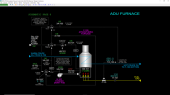
Basic Controls: ADU Furnace
TIC-100 controls the crude oil temperature leaving the radiant coils of ADU Furnace, F-100, by adjusting the position of fuel gas control valve TV-100. The flow of fuel gas to F-100 is indicated on FI-101. TIC-100 is locked in manual mode with an output of 0% when F-100 Interlock I-100 is in the TRIP state as indicated on XA-100.
Switch HS-102 controls the motor of Forced Draft Fan, K-102. The motor status is a trip input to I-100. BS-101 detects a flame/flameout condition of the fuel gas burners of F-100 and is also a trip input to I-100.
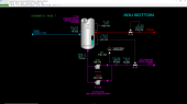
Basic Controls: ADU Bottom
T-100 bottoms liquid is collected and sent to the Vacuum Distillation Unit (VDU) by Bottoms Pumps, P-114/P-114B, whose motors are controlled by switches HS-114/HS-114B, respectively. LIC-114 controls the bottom level by adjusting the position of LV-114. The bottoms flow to the VDU is indicated by FI-124 and its temperature is indicated by TI-114. FAL-124 is an indicating switch of the low alarm status of FI-124 and is a trip input to the VDU Furnace Firing Interlock, I-200.
Stripping steam is injected into the ADU bottoms by FIC-134 which adjusts the position of FV-134. The pressure at the bottom of T-100 is indicated on PI-114.
The pressure difference across the flash zone (trays 19 and 20) is indicated on PDI-114. A low differential pressure usually indicates insufficient overflash liquid is coming from the Gas Oil section.
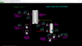
Basic Controls: Gas Oil System
Hot gas oil flows by gravity to the Gas Oil Stripper, T-113, through FIC-113 which adjusts the position of FV-113. The temperature of the gas oil draw is indicated on TI-113.
The gas oil enters the stripper at the top and flows downward over six trays. Stripping steam is introduced into the bottom of the stripper through FIC-133 which adjusts the position of FV-133. The gas oil product is pumped from the base of the stripper by the Gas Oil Product Pumps, P-113/P-113B, whose motors are operated by switches HS-113/HS-113B, respectively. The gas oil product flow is controlled by LIC-113 which adjusts the position of LV-113. The temperature of the gas oil from the stripper is indicated on TI-123 and the flow of gas oil to storage is indicated on FI-123. The gas oil product's 95% volume boiling point is indicated on AI-123. A significantly lower boiling point than normal indicates excessive kerosene is coming from the kerosene section. A significantly higher boiling point than normal indicates the gas oil draw flow from T-100 is too high.
Circulating gas oil is pumped by Gas Oil Pumparound Pumps, P-117/P-117B, whose motors are controlled by switches HS-117/HS-117B, respectively. The temperature of the circulating gas oil from T-100 is indicated on TI-117A and the return temperature from E-106 is indicated TI-117B. The flow of circulating gas oil is controlled by FIC-117 which adjusts the position of FV-117. FV-117 will fully open on a loss of instrument air. The differential pressure across the gas oil section of T-100 is indicated on PDI-113.
Basic Controls: Kerosene System
Hot kerosene flows by gravity to the Kerosene Stripper, T-112, through FIC-112 which adjusts the position of FV-112. The temperature of the kerosene draw is indicated on TI-112.
The kerosene enters the stripper at the top and flows downward over six trays. Stripping steam is introduced into the bottom of the stripper through FIC-132 which adjusts the position of FV-132. The kerosene product is pumped from the base of the stripper by the Kerosene Product Pumps, P-112/P-112B, whose motors are operated by switches HS-112/HS-112B, respectively. The kerosene product flow is controlled by LIC-112 which adjusts the position of LV-112. The temperature of the kerosene from the stripper is indicated on TI-122 and the flow of kerosene to storage is indicated on FI-122. The kerosene product's 95% volume boiling point is indicated on AI-122. A significantly lower boiling point than normal indicates excessive naphtha is coming from the naphtha section. A significantly higher boiling point than normal indicates the kerosene draw flow from T-100 is too high.
Circulating kerosene is pumped by Kerosene Pumparound Pumps, P-116/P-116B, whose motors are controlled by switches HS-116/HS-116B, respectively. The temperature of the circulating kerosene from T-100 is indicated on TI-116A and the return temperature from E-105 is indicated TI-116B. The flow of circulating kerosene is controlled by FIC-116 which adjusts the position of FV-116. FV-116 will fully open on a loss of instrument air. The differential pressure across the kerosene section of T-100 is indicated on PDI-112.
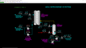
Basic Controls: Naphtha System
Hot naphtha flows by gravity to the Naphtha Stripper, T-111, through FIC-111 which adjusts the position of FV-111. The temperature of the kerosene draw is indicated on TI-111.
The naphtha enters the stripper at the top and flows downward over six trays. Stripping steam is introduced into the bottom of the stripper through FIC-131 which adjusts the position of FV-131. The naphtha product is pumped from the base of the stripper by the Naphtha Product Pumps, P-111/P-111B, whose motors are operated by switches HS-111/HS-111B, respectively. The naphtha product flow is controlled by LIC-111 which adjusts the position of LV-111. The temperature of the naphtha from the stripper is indicated on TI-121 and the flow of naphtha to storage is indicated on FI-121. The naphtha product's 95% volume boiling point is indicated on AI-121. A significantly lower boiling point than normal indicates excessive gasoline is being refluxed to the top of T-100. A significantly higher boiling point than normal indicates the naphtha draw flow from T-100 is too high.
Circulating naphtha is pumped by Naphtha Pumparound Pumps, P-115/P-115B, whose motors are controlled by switches HS-115/HS-115B, respectively. The temperature of the circulating naphtha from T-100 is indicated on TI-115A and the return temperature from E-104 is indicated TI-115B. The flow of circulating naphtha is controlled by FIC-115 which adjusts the position of FV-115. FV-115 will fully open on a loss of instrument air. The differential pressure across the naphtha section of T-100 is indicated on PDI-111.
The final return temperature of circulating naphtha is controlled by TIC-115 which adjusts the position of three-way control valve TV-115. On a loss of instrument air, TV-115 will open fully toward E-115. The temperature of the cooling water supply to E-115 is indicated on TI-131 and the temperature leaving E-115 is indicated on TI-132.
Basic Controls: ADU Overhead
The temperature of the vapor leaving the top of T-100 is controlled by TIC-110 whose output adjusts the setpoint of top reflux flow controller FIC-110 which adjust the position of FV-110. FV-110 will fully open on a loss of instrument air. The pressure at the top of T-100 is indicated on PI-110.
The Atmospheric Distillation Unit (ADU) overhead vapor combines with hot recycle gas from Gas Compressor, K-130, before entering Overhead Condenser, E-110. The temperature of the combined gas is indicated on TI-119 and the outlet temperature of the process is indicated on TI-120. Cooling water flow to E-110 is controlled by switch HV-110 which opens and closes HV-110. The temperature of cooling water supply to E-110 is indicated on TI-133 and the outlet temperature is indicated on TI-134.
Gasoline is pumped from the Overhead Reflux Drum, D-111, by Overhead Pumps, P-110/P-110B, whose motors are controlled by switches HS-110/HS-110B, respectively. The temperature of gasoline leaving D-111 is indicated on TI-127. The level of gasoline in D-111 is controlled by LIC-110 which sends gasoline product to storage by adjustment of LV-110. The flow of product gasoline is indicated by FI-120 and the Reid vapor pressure of the gasoline is indicated on AI-120. LAH-110 is an independent indicator of the level of the gasoline in D-111 and is a trip input to the Gas Compressor Interlock, I-130.
Water collected in the boot of D-111 is pumped to the sour water treating system at battery limits by Sour Water Pumps, P-120/P-120B, whose motors are operated by switches HS-120/HS-120B, respectively. LIC-120 controls the boot’s sour water level by adjusting the position of LV-120. The flow of sour water to battery limits is indicated on FI-125.
The separated gas from D-111 is compressed by Gas Compressor, K-130, whose motor is operated by switch HS-130, and sent to a sour gas treating unit at battery limits for eventual use as a fuel gas. PIC-120 controls the pressure of D-111 by recirculating some of the compressed gas through PV-130 and back to E-110. The flow of gas through K-130 is indicated on FI-131. The discharge pressure of K-130 is indicated on PI-130 and the discharge temperature is indicated on TAH-130, which serves as a trip sensor to I-130. Switch HV-135 opens and closes the block valve HV-135 on the line from K-130’s discharge to the treater at battery limits. The flow of gas to the treater is indicated on FI-130. The propane content of the gas is indicated on AI-130.
The separated gas from D-111 is compressed by Gas Compressor, K-130, whose motor is operated by switch HS-130, and sent to a sour gas treating unit at battery limits for eventual use as a fuel gas. PIC-120 controls the pressure of D-111 by recirculating some of the compressed gas through PV-130 and back to E-110. The flow of gas through K-130 is indicated on FI-131. The discharge pressure of K-130 is indicated on PI-130 and the discharge temperature is indicated on TAH-130, which serves as a trip sensor to I-130. Switch HV-135 opens and closes the block valve HV-135 on the line from K-130’s discharge to the treater at battery limits. The flow of gas to the treater is indicated on FI-130. The propane content of the gas is indicated on AI-130.
Hand controller HIC-131 allows adjustment of the flow through Gas Compressor, K-130. Normally the output of HIC-131 is 25%. If the amount of gas produced by the ADU exceeds the capacity of K-130 when HIC-131 is at 100% output or if K-130 is out of service, HIC-130 can be used to route gas to the flare by opening HV-130.
Basic Controls: VDU Furnace
TIC-200 controls the temperature of feed leaving the radiant coils of Vacuum Distillation Unit (VDU) Furnace, F-200, by adjusting the position of fuel gas control valve TV-200. The flow of fuel gas to F-200 is indicated on FI-201. TIC-200 is locked in manual mode with an output of 0% when F-200 Interlock I-200 is in the TRIP state as indicated on XA-200.
Switch HS-202 controls the motor of Forced Draft Fan, K-202. The motor status is a trip input to I-200. BS-201 detects a flame/flameout condition of the fuel gas burners of F-200 and is also a trip input to I-200. Refer to VDU Interlocks below for the operation of interlock I-200.
Basic Controls: VDU Bottom
Bottoms liquid (vacuum residue) is collected and sent to storage by VDU Bottoms Pumps, P-214/P-214B, whose motors are controlled by switches HS-214/HS-214B, respectively. LIC-214 controls the bottom level by adjusting the position of LV-214. The bottoms flow to storage is indicated by FI-224 and its temperature is indicated by TI-214. The vacuum residue's 95% point is indicated by AI-224.
Stripping steam is injected into the bottom of T-200 by FIC-234 which adjusts the position of FV-234. The pressure drop across the trays of the stripping section is indicated on PDI-215. The VDU bottom pressure is indicated by PI-214.
The flow of wash oil (slop wax) to the flash zone of T-200 is controlled by FIC-233 which adjusts the position of FV-233. The pressure drop across the flash zone packing is indicated on PDI-214. A low differential pressure suggests insufficient wash oil flow.
Basic Controls: VDU Slop Wax System
Hot slop wax is pumped from T-200 by Slop Wax Pumps, P-213/P-213B, whose motors are operated by HS-213/HS-213B, respectively. The slop wax product flow to storage is indicated on FI-223. The flow is controlled by LIC-213 which controls the slop wax pan level by adjusting the position of LV-213. The 95% volume boiling point of the slop wax product is indicated by AI-223. The temperature of cooled slop wax from E-213 is indicated by TI-223. The slop wax pumparound flow is controlled by FIC-213 which adjusts the position of FV-213. FV-213 will fully open on a loss of instrument air. Wash Oil to the flash zone is controlled by FIC-233 by adjusting the position of FV-233.
The temperature of slop wax on the slop wax pan is indicated by TI-213. The pressure drop across the packing of the slop wax section is indicated on PDI-213.
Basic Controls: VDU HVGO System
Hot Heavy Vacuum Gas Oil (HVGO) is pumped from T-200 by HVGO Pumps P-212/P-212B whose motors are operated by HS-212/HS-212B, respectively. The HVGO product flow to storage is indicated on FI-222. The flow is controlled by LIC-212 which controls the HVGO pan level by adjusting the position of LV-212. The 95% volume boiling point of the HVGO product is indicated by AI-222. The temperature of cooled HVGO from E-212 is indicated by TI-222. The HVGO pumparound flow is controlled by FIC-212 which adjusts the position of FV-212. FV-212 will fully open on a loss of instrument air. HVGO reflux to the slop wax system is controlled by FIC-232 by adjusting the position of FV-232.
The temperature of HVGO on the HVGO pan is indicated by TI-212. The pressure drop across the packing of the HVGO section is indicated on PDI-212.
Basic Controls: VDU LVGO System
Hot Light Vacuum Gas Oil (LVGO) is pumped from T-200 by LVGO Pumps, P-211/P-211B, whose motors are operated by HS-211/HS-211B, respectively. The LVGO product flow to storage is indicated on FI-221. The flow is controlled by LIC-211 which controls the LVGO pan level by adjusting the position of LV-211. The 95% volume boiling point of the LVGO product is indicated by AI-221. The LVGO pumparound flow is controlled by FIC-211 which adjusts the position of FV-211. FV-211 will fully open on a loss of instrument air. LVGO reflux to the HVGO system is controlled by FIC-231 by adjusting the position of FV-231.
The temperature of cooled LVGO from E-211 is indicated by TI-221. TIC-231 controls the LVGO pumparound return temperature by adjusting the position of three-way valve TV-231. TV-231 will open fully toward E-211 on a loss of instrument air.
The temperature of LVGO on the LVGO pan is indicated by TI-211. The pressure drop across the packing of the LVGO section is indicated on PDI-211. The temperature of vapor leaving the top of T-200 is indicated on TI-210.
Basic Controls: VDU Overhead
The VDU overhead vapor from T-200 flows through the Vacuum Pre-condenser, E-210, where a portion of the steam and any residual hydrocarbons are condensed before entering Ejector, EJ-210. These liquids are drained by gravity to the Vacuum Drum. A seal loop in the condensate piping prevents vapor blow-through to the Vacuum Drum. Cooling water flow through E-210 and Vacuum Condenser, E-209, is regulated by HV-212.
Steam to Ejector, EJ-210, is regulated by HV-211. The Ejector compresses the vapor from E-210 using steam as a motive fluid. The vapor and motive steam combine and are sent to Vacuum Condenser E-209 to condense the steam and any residual hydrocarbons from E-210.
The liquids and vapor from E-209 and E-210 are separated in Vacuum Drum, D-211. Hydrocarbons are separated from the water by gravity and float on the water side and fall over the internal weir. The water interface level LIC-210 is normally controlled at 50% by pumping the water to treatment facilities with P-210/P-210B whose motors are controlled by HS-210/HS-210B, respectively. LIC-210 adjusts the position of LV-210. The top of the weir is reached at 80% level indication on LIC-210.
The hydrocarbon phase on the opposite side of the weir in D-211 slowly accumulates and its level is indicated on LI-209. When a sufficient level of slop oil has accumulated, the level can be drained to slop facilities via P-209/P-209B whose motors are operated by HS-209/HS-209B, respectively.
The VDU vacuum pressure is controlled by PIC-210 which recirculates cooled vapor from D-211 to the suction of Ejector, EJ-211, by adjusting the position of PV-210.
I-100 - F-100 Firing Interlock
Protection Logic
I-100 protects the Atmospheric Distillation Unit (ADU) Furnace, F-100, from potential damage by stopping fuel gas to the furnace if any of the following occurs:
- Low crude feed flow (FIC-100 will alarm on low flow, FAL-100 will move to the TRIP state)
- Loss of flame detection (BS-101 is in the OUT state, XA-101 will alarm)
- Forced Draft Fan K-102’s motor is off (HS-102 is in the OFF state, XA-102 will alarm)
If any if these conditions occur, switch XI-100 will indicate the TRIP state and cause I-100 to activate (XA-100 will alarm and indicate the TRIP state). When I-100 activates it will lock F-100 outlet temperature controller, TIC-100, in manual mode with an output of 0% to close TV-100, thereby stopping fuel gas to F-100.
Starting Fuel Firing
To start fuel gas to F-100, all the trip inputs to I-100 as indicated on XI-100 must be cleared first. Because there is no fuel gas to F-100 and, therefore, no flame is possible, the flame detection switch BS-101 must be bypassed by placing bypass switch HS-101 in the BYPAS position. Additionally, crude flow must be above the low alarm setting of FIC-100 and the motor for K-102 must be running to start fuel gas.
In order to reset the interlock, F-100 must be purged with air for a preset time (normally 120 seconds). The purge timer will start counting down when K-102’s motor is running and XI-100 indicates no trip inputs are active. The countdown time is indicated on XI-102T. When this time becomes zero, XI-102 will indicate the purge of F-100 is complete and will reset I-100 (XA-100 will indicate OK) and controller TIC-100 will be unlocked for control by the operator.
Before starting fuel gas using TIC-100, the ignition system for F-100 must be turned on using switch HS-103 to light off added fuel gas. When HS-103 is turned to the ON state, it will generate an alarm as a reminder that the ignition system should be turned off after F-100 firing is established.
After turning the ignition system on, adjust the output of TIC-100 to 5% to establish a small flow of fuel gas as indicated on FI-101. Verify the burners light off by watching BS-100 change from the OUT state to the FLAME state.
Once a fuel gas flow is detected, I-100 will automatically change the flame detection bypass switch HS-101 from the BYPAS state to the NORM state after 10 seconds to re-enable protection of F-100 from a flameout. If the burners fail to stay ignited after 10 seconds, I-100 will activate and HS-101 will have to be set to the BYPAS position again in order to start the purge timer which will, in turn, reset I-100.
Make sure the burner ignition system switch HS-103 is in the ON position when fuel gas flow is established. If F-100 firing cannot be established after two attempts using the correct procedure, then it is likely the flame sensor needs to be checked.
I-130 - Gas Compressor K-130 Interlock
Protection Logic
I-130 protects the Gas Compressor, K-130, from conditions that could potentially damage it by stopping its motor, KM-130, if any of the following conditions occur:
- D-111 level as indicated on LAH-110 exceeds 95%
- K-130 discharge temperature TAH-130 exceeds 250 DEG F
If any if these conditions occur, switch XA-130 will indicate the TRIP state, generate an alarm and cause I-130 to activate. When I-130 activates it will lock KM-130’s motor switch, HS-130, in the STOP position.
Starting the Compressor
I-130 will automatically reset once all the trip inputs have returned to the non-trip states. Use HS-130 to start the compressor motor.
F-200 Firing Interlock
Protection Logic
I-200 protects the VDU Furnace, F-200, from potential damage by stopping fuel gas to the furnace if any of the following occurs:
- Low feed flow (FIC-124 will alarm on low flow, FAL-124 will move to the TRIP state)
- Loss of flame detection (BS-201 is in the OUT state, XA-201 will alarm)
- Forced Draft Fan K-202’s motor is off (HS-202 is in the OFF state, XA-202 will alarm)
If any if these conditions occur, switch XI-200 will indicate the TRIP state and cause I-200 to activate (XA-200 will alarm and indicate the TRIP state). When I-200 activates it will lock F-200 outlet temperature controller TIC-200 in manual mode with an output of 0% to close TV-200, thereby stopping fuel gas to F-200.
Starting Fuel Firing
To start fuel gas to F-200, all the trip inputs to I-200 as indicated on XI-200 must be cleared first. Because there is no fuel gas to F-200 and, therefore, no flame is possible, the flame detection switch BS-201 must be bypassed by placing bypass switch HS-201 in the BYPAS position. Additionally, feed flow must be above the low alarm setting of FIC-124 and the motor for K-202 must be running to start fuel gas.
In order to reset the interlock, F-200 must be purged with air for a preset time (normally 120 seconds). The purge timer will start counting down when K-202’s motor is running and XI-200 indicates no trip inputs are active. The countdown time is indicated on XI-202T. When this time becomes zero, XI-202 will indicate the purge of F-200 is complete and will reset I-200 (XA-200 will indicate OK) and controller TIC-200 will be unlocked for control by the operator.
In order to reset the interlock, F-200 must be purged with air for a preset time (normally 120 seconds). The purge timer will start counting down when K-202’s motor is running and XI-200 indicates no trip inputs are active. The countdown time is indicated on XI-202T. When this time becomes zero, XI-202 will indicate the purge of F-200 is complete and will reset I-200 (XA-200 will indicate OK) and controller TIC-200 will be unlocked for control by the operator.
Before starting fuel gas using TIC-200, the ignition system for F-200 must be turned on using switch HS-203 to light off added fuel gas. When HS-203 is turned to the ON state, it will generate an alarm as a reminder that the ignition system should be turned off after F-200 firing is established.
After turning the ignition system on, adjust the output of TIC-200 to 5% to establish a small flow of fuel gas as indicated on FI-201. Verify the burners light off by watching BS-201 change from the OUT state to the FLAME state.
Once a fuel gas flow is detected, I-200 will automatically change the flame detection bypass switch HS-201 from the BYPAS state to the NORM state after 10 seconds to re-enable protection of F-200 from a flameout. If the burners fail to stay ignited after 10 seconds, I-200 will activate and HS-201 will have to be set to the BYPAS position again in order to start the purge timer which will, in turn, reset I-200.
Make sure the burner ignition system switch HS-203 is in the ON position when fuel gas flow is established. If F-200 firing cannot be established after two attempts using the correct procedure, then it is likely the flame sensor needs to be checked.