Process Description
The purpose of the Hydrodesulfurization Unit (HDS) is to remove sulfur and other undesirable compounds from distillates to meet specifications for use as a fuel or as a feed to another refinery process.
Importance HDS units are increasing in their importance owing to ever-tightening environmental restrictions on the concentration of sulfur allowed in liquid fuels and due to the increasing need to process petroleum distillates further in downstream catalytic units that require clean feeds to avoid poisoning the catalysts used in those processes. Therefore, the loss of or sub-optimal operation of a HDS unit can result in a large loss of revenue to an operating company.
The HDS process consists of two main sections: the Reactor Section and the Stabilizer Section.
Major Equipment
The Reactor Section consists of:
- Feed Surge Drum, D-101
- Reactor Feed Pumps, P-101A/B
- Hydrogen Compressor, K-101
- Reactor Feed/Effluent Heat Exchanger, E-101
- Reactor Feed Heater, F-101
- Hydrodesulfurization Reactor, R-101
- Reactor Effluent Air Cooler, E-102
- Reactor Effluent Separator, D-102
- H2S Absorber, T-101
- Recycle Compressor Knockout (KO) Drum, D-103
- Recycle Compressor, K-102
The Stabilizer Section consists of:
- Stabilizer Feed/Bottoms Heat Exchanger, E-103
- Stabilizer Column, T-102
- Overhead Condenser, E-104
- Stabilizer Reflux Drum, D-104
- Stabilizer Reflux Pumps, P-102A/B
- Stabilizer Reboiler, E-105
- Reboiler Condensate Pot, D-105
- Stabilizer Bottoms Pumps, P-103A/B
- Product Cooler, E-106
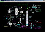
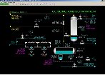
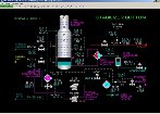
Process Overview: Reactor Section
Sulfur-containing distillate is received from battery limit and fed to the Feed Surge Drum, D-101 and pumped from D-101 by Reactor Feed Pumps P-101A/B to the Reactor Feed/Effluent Heat Exchanger E-101. The design feed flow is 20.0 MBPD of virgin naphtha with a sulfur concentration of 0.05 weight %. Makeup hydrogen from Hydrogen Compressor K-101 and recycle gas from Recycle Compressor K-102 are combined with the distillate feed prior to entering E-101. The design concentration of feed hydrogen is 75 volume % and the design flow is 1.372 MMSCF/H. In the design operation on naphtha, the Recycle Compressor is not in service.
The feed/gas mixture is preheated in E-101 from 188 DEG F to 470 DEG F using hot effluent from Hydrodesulfurization Reactor R-101. The preheated mixture is sent to the Reactor Feed Heater F-101.
F-101 is a gas-fired process heater with two separate tube passes. When the feedstock is naphtha, the heater will vaporize the feed mixture completely at the design outlet conditions of 550 DEG F and 390 PSIG. With heavier feedstocks there may not be complete vaporization. The degree of feed liquid vaporization also depends on the pressure of the reactor loop and the outlet temperature of F-101. When operating on gas oil feed with 1.5 weight % sulfur, the outlet temperature of F-101 can be as high as 750 DEG F to attain good sulfur conversion. The outlets of the two passes from F-101 are combined and sent to the top of the HDS Reactor R-101.
Process Overview: Reactor Beds
R-101 is a fixed-bed reactor employing conventional hydrotreating catalysts designed for sulfur removal. The solid particles of the two reactor beds are porous which increases the available surface area for the feed/hydrogen mixture to contact the active metal catalysts within the particles. The hydrodesulfurization reaction results in hydrogen combining with sulfur bearing compounds that are contained in the distillate feed. This reaction results in the liberation of the chemically bound sulfur as hydrogen sulfide (H2S). A large amount of catalyst and high temperature and pressure are required because the reaction rate is very low. The hydrodesulfurization reaction also releases heat.
When required, a quench flow of recycle gas from the Recycle Compressor K-102 cools the mixture leaving the top catalyst bed of R-101 before it enters the bottom bed of catalyst. In the design feed naphtha case, the temperature rise across the top bed is only 4 DEG F owing to the low sulfur concentration of the feed. However, when operating with the maximum feed sulfur concentration of 1.5 weight % in gas oil, the temperature rise of the top bed will be about 28 DEG F.
The bottom bed consists of catalyst optimized for other hydrotreating reactions (e.g. conversion of nitrogen containing compounds to ammonia). These other reactions are not simulated because their concentrations and subsequent effects are usually small relative to those of sulfur. When operating on the design naphtha feedstock there is a negligible temperature rise across the bottom bed because nearly all the sulfur is reacted in the top bed. In the case of operation with maximum sulfur in the feed, the temperature rise across the bottom bed will be about 13 DEG F.
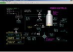
Process Overview: Reactor Bottom
The effluent from the bottom of R-101 at 554 DEG F is sent to the Reactor Feed/Effluent Heat Exchanger E-101 to preheat the feed and to condense a large portion of the vaporized distillate leaving R-101. The outlet of the reactor effluent side of E-101 at design operation on naphtha is 260 DEG F and is passed to Reactor Effluent Air Cooler, E-102 to cool and condense the remainder of the treated distillate. The normal outlet temperature of E-102 is 130 DEG F. Most of the hydrogen remains in the vapor phase at the outlet of E-102 and is separated from the condensed treated distillate in Reactor Effluent Separator D-102. Water is normally injected into the feed to E-102 to remove ammonia, hydrogen chloride and any organic salts which may be present in the treated distillate. The normal water injection rate is 20 GPM. This water is also separated out in the boot section of D-102 and is sent to a treating unit.
D-102 normally operates at 378 PSIG. The separated gas from D-102 is passed through the H2S Absorber T-101 to remove any hydrogen sulfide prior to releasing the gas to the fuel system and before recycling the gas. An amine solution is used to absorb the hydrogen sulfide by contacting the gas over a packed bed that intimately contacts the gas and liquid. T-101 can be partially or completely bypassed to control the hydrogen sulfide concentration of the purge/recycle gas. The normal gas flow to T-102 is about 1.343 MMSCF/H with an H2S concentration of 620 volume ppm. The gas is treated with amine solution at a rate of 30 GPM which reduces the H2S concentration below 1 volume ppm.
The outlet gas from T-101 is sent to the Recycle Compressor Knockout Drum D-103 to remove any liquids that may carry over from T-101 or D-102 prior to sending the separated gas to the fuel system (purge gas) or to the Recycle Compressor K-102. A purge flow of sweetened gas from T-101 is taken off under pressure control to the fuel gas system. D-103 normally operates at 375 PSIG.
Process Overview: recycle Compressor
The Recycle Compressor is used during startup to help heat up the HDS Reactor R-101 and to help sulfide newly installed catalyst, if required. The Recycle Compressor is also used when higher sulfur feeds are being processed. Recycling hydrogen-rich gas from the reactor effluent increases the hydrogen concentration at the HDS Reactor inlet and thereby improves sulfur conversion to H2S. The Recycle Compressor discharges most of its flow to Reactor Feed/Effluent Heat Exchanger E-101. Depending on conditions, a portion of the recycle gas will be used as a quench agent in the HDS Reactor. In the case of gas oil feed with a sulfur feed concentration of 1.5 weight % and a reactor inlet temperature of 750 DEG F, the total flow of recycle gas is 1.484 MMSCF/H with about 30% of that used as quench gas for R-101.
When the Recycle Gas compressor is out of service, the mode of operation of the Reactor Section is referred to as “once-through mode”. This is the normal mode of operation for naphtha feeds with lower sulfur concentrations.
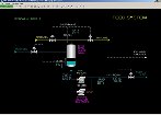
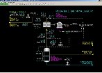
Process Overview: Stabilizer Section
Condensed, treated distillate collected in Reactor Effluent Separator D-102 contains a fairly significant fraction of dissolved hydrogen, hydrogen sulfide and other light gases owing to the elevated pressure of the Reactor Section. As such, the treated distillate cannot be sent directly to storage, used as a fuel or sent to other process units. To remove these light gases (i.e. to stabilize the treated product) the liquid is sent to the Stabilizer Column T-102 where it undergoes distillation to separate out the lighter components as a product overhead gas. The stabilized distillate product is sent off to storage.
Alternatively, heavier distillates such as gas oil cannot be easily boiled using steam as the heat supply for the Stabilizer Column. In this case, the Stabilizer Column can be run as a stripper using natural gas as a stripping agent to remove the light gases.
Process Overview: Stabilizer Column Feed
The cool, unstabilized distillate from D-102 is heated from 130 DEG F to 353 DEG F in Stabilizer Feed/Bottoms Heat Exchanger E-103 using hot stabilized product from the bottom of the Stabilizer Column T-102. The flow rate of treated naphtha distillate from D-102 is 20.7 MBPD.
Heated, unstabilized distillate from E-103 enters Stabilizer Column T-102 onto tray 15. T-102 operates at 105 PSIG which is much lower than the pressure in D-102. Because of the lower pressure and high temperature, the distillate flashes into a vapor fraction and a liquid fraction as it enters T-102. The vapor fraction mainly contains hydrogen, hydrogen sulfide and any other light gases that were dissolved in the treated distillate leaving D-102. The vapor fraction flows up through the top section of T-102 where any recoverable lighter distillate will be washed down the Stabilizer Column by reflux. The liquid fraction of the feed entering T-102 will fall through the bottom section of T-102 where vapor generated by Reboiler E-105 will strip any unflashed hydrogen and other light gases.
Process Overview: Stabilizer Column Bottoms
Distillate leaving the bottom-most tray of T-102 is routed into the bottom of the supply sump for Stabilizer Reboiler E-105. The supply sump is formed by segmenting off a portion of the bottom of the T-102 using a baffle. E-105 uses 17.9 KPPH of 650 PSIG steam as a heating medium.
E-105 is designed as a thermosiphon reboiler so that the liquid from the inlet sump naturally circulates through the heat exchanger as the liquid is vaporized in the tubes of the reboiler. The circulating liquid is partially vaporized by steam applied to the shell side of E-105. The outlet liquid separates into a liquid and vapor fraction as it reenters T-102. The vapor flows up into the bottom tray of T-102 while the liquid fraction is returned to the top of the reboiler inlet sump. Excess liquid from the top of the sump flows over the top edge of the sump baffle into the base of T-102 where it is removed as stabilized product.
When feeds are too heavy to be significantly vaporized with steam, natural gas can be injected into the bottom of T-102 to act as a stripping agent for removing H2S, hydrogen and residual water from the unstabilized feed to T-102. It is also possible to simultaneously warm the distillate by applying steam in E-105. Along with the stripping gas, warmer temperatures help release any dissolved gases reaching the bottom of T-102.
The hot, stabilized product from the bottom of T-102 is pumped out by Stabilizer Bottoms Pumps P-103A/B. The hot product at 423 DEG F is cooled in Stabilizer Feed/Bottoms Heat Exchanger E-103 before reaching the pumps to ensure there will not be any problems with excessively hot liquid flashing at the pumps’ suction. The treated product leaves E-103 at 200 DEG F and is pumped through Product Cooler E-106 and sent to storage. E-106 uses cooling water as its cooling fluid. The product is cooled down to 118 DEG F in E-106.
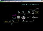
Process Overview: Stabilizer Column Overhead
Vapor leaves the top of T-102 at 197 DEG F and flows through Overhead Condenser E-104 which is cooled using cooling water. The process stream leaves E-104 at 100 DEG F. Most of the light gases stripped from the feed remain as vapor leaving E-104 and are separated from the liquid in Stabilizer Reflux Drum D-104. A small portion of the gases still dissolve in the overhead liquid, but after they are refluxed to T-102 they will recycle back up the top of T-102 and through E-104 until they are completely removed in D-104.
Stabilizer Reflux Drum D-104 separates the vapor, hydrocarbon liquid and liquid water phases leaving E-102. The vapor is taken off as sour gas (contains hydrogen sulfide) to the fuel gas treater for removal of H2S prior to use as a fuel gas. The design rate of sour gas is 44.1 MSCFH. D-104 normally operates at 100 PSIG but can operate at lower pressures during gas stripping to improve gas release from the treated product.
The hydrocarbon liquid collected in D-104, which mainly consists of propane, butane and pentane, is refluxed back to T-102 under level control. Stabilizer Reflux Pumps P-102A/B are used to pump the reflux back up to the top of T-102. Normally, all of the liquid is refluxed to T-102. If desired, a portion of the reflux can be taken off to storage. This permits extraction of lighter liquid components out of the treated product entering T-102.
Normally, the amount of water reaching D-104 is very small. This water is collected in the boot of D-104 and taken off to the sour water treating unit.
Instrumentation
Basic Controls: Feed System
LIC-101 controls the level of feed distillate in the Feed Surge Drum D-101 by adjusting the opening of the feed supply valve LV-101.
PIC-101 controls the pressure of the nitrogen blanket of D-101 by adjusting the nitrogen supply valve PV-101A or the vent to flare valve PV-101B via a split-range control. When the output of PIC-101 is 50% both valves are closed. When the output moves to 100%, PV-101A fully opens and PV-101B stays closed. When the output moves to 0%, PV-101A stays closed and PV-101B fully opens.
HS-101A/B are switches that control the motors of Reactor Feed Pumps P-101A/B, respectively. If a motor trips, the respective switch will move to the STOP state.
FIC-101 controls the flow of feed from P-101A/B to Reactor Feed/Effluent Heat Exchanger E-101 via FV-101 on the discharge line from the pumps. It is assumed a local minimum flow controller protects the pumps against damage from dead-heading the pumps by closure of FV-101.
The process value of FIC-101 is sent to the calculation of FAL-106.
TI-101 indicates the temperature of the feed drawn from D-101.
AI-101 indicates the sulfur content of the feed in weight %.
Basic Controls: Hydrogen Compressor
HS-102 is a switch that controls the motor of Hydrogen Compressor K-101. If the motor trips, HS-102 will move to the STOP state.
HIC-102 adjusts the flow of K-101 using a suction valve unloading system that permits continuous capacity control of the reciprocating compressor. This is accomplished by momentarily holding open the suction (inlet) valves of the compressor (there are separate valves to each side of the double-acting piston). The system allows the operator to adjust the time the valves are momentarily held open. When HIC-102 output is 0% the suction valves are continuously held open and no gas is compressed as the suction gas is allowed to move freely in and out of the cylinder of the compressor. When HIC-102 output is 100% the suction valves are never held open by the system and full flow of the compressor is achieved. The system is calibrated to make compressor flow respond nearly linearly with respect to the output of HIC-102.
HIC-103 is used to adjust the opening of the discharge valve HV-103 of the Hydrogen Compressor. HV-103 should normally be 100% open when the compressor is operating.
PI-102 indicates the pressure of the supply hydrogen.
TI-102 indicates the temperature of the supply hydrogen.
AI-102 indicates the hydrogen concentration of the supply hydrogen in volume %.
PI-103 indicates the compressor discharge pressure.
TI-103 indicates the compressor discharge temperature. TAH-103 indicates the same and is an independent sensor for the protective system of the compressor.
FI-103 indicates the flow through HV-103 to E-101. Its process value is sent to the calculation for FAL-106.
XA-102B indicates the status of the mechanical monitoring system of the compressor and is tied into the protective system of the compressor.
Basic Controls: Feed Heating, E-101
HIC-104 is used to adjust the nitrogen supply valve HV-104. This is normally used during startup and shutdown to sweep hydrogen and oxygen out of the Reactor Section. The pressure of the nitrogen supply is 100 PSIG.
HIC-108 is used to bypass some cold feed around Reactor Feed Effluent Exchanger E-101 with HV-108. This bypass is used when the temperature rise of the HDS Reactor R-101 is so large it reduces the fuel gas required in Reactor Feed Heater F-101 to the point where it is no longer possible to control the reactor inlet temperature. Opening HIC-108 will cause a higher heat load on Reactor Effluent Air Cooler E-102.
PI-106 indicates the pressure of the mixed feed to E-101. PAH-106 indicates the same and is an independent sensor for the protective system of the Reactor Feed Heater F-101.
TI-106 indicates the temperature of the mixed feed to E-101.
TI-107 indicates the outlet temperature of the mixed feed from E-101.
TI-115 indicates the outlet temperature of R-101 which feeds to the hot side of E-101.
Basic Controls: Feed Heating, F-101
TI-108 indicates the inlet temperature of the mixed feed to F-101.
FAL-106 indicates the computed flow for the protective system of the Reactor Feed Heater F-101 (see Interlocks). It is expressed as a % of trip setpoint and accounts for operation in gas-only, liquid-only and mixed feed modes.
HIC-112A adjusts the valve position of HV-112A on the “A” tube pass through F-101. HV-112A is outfitted with a mechanical minimum stop set at 30% to avoid accidental no-flow through the tube pass either by operator misoperation or valve failure.
HIC-112B adjusts the valve position of HV-112B on the “B” tube pass through F-101. HV-112B is also outfitted with a mechanical minimum stop set at 30%.
TI-110A indicates the outlet temperature of the “A” tube pass of F-101.
TI-110B indicates the outlet temperature of the “B” tube pass of F-101.
TIC-110 controls the combined outlet temperature of F-101 by adjusting the setpoint of the fuel gas flow controller FIC-110. The setpoint of TIC-110 tracks its PV when in MANUAL mode. The protective system for F-101 will lock TIC-110 in MANUAL mode if the trip is active.
FIC-110 controls the fuel gas flow to F-101 via FV-110. It is normally in CASCADE mode and receives its setpoint from TIC-110. When it is in AUTOMATIC or MANUAL mode, it will initialize the output of TIC-110 to maintain bumpless control when placed into CASCADE mode. When in MANUAL mode, the setpoint of FIC-110 will track its PV. The protective system for F-101 will lock FIC-110 in MANUAL mode with an output of 0% if the trip is active.
TAH-110 is an independent sensor of the combined outlet temperature of F-101 for the protective system of the Reactor Feed Heater F-101.
Basic Controls: HDS Reactor
PI-110 indicates the pressure of the feed to HDS Reactor R-101. PAH-110 indicates the same and is an independent sensor for the protective system of the Reactor Feed Heater F-101.
TI-112A/B/C indicate the top bed temperatures of R-101. They indicate at the same bed depth but vary radially by 120 degrees. TAH-112A/B/C indicate the same and are independent sensors for the protective system of the Reactor Feed Heater F-101.
PDI-111 indicates the pressure drop across the top bed of R-101.
TIC-113 controls the outlet temperature from the inter-bed quench system by adjusting the setpoint of the recycle gas quench flow controller FIC-113. The setpoint of TIC-113 tracks its PV when in MANUAL mode.
FIC-113 controls the recycle gas quench flow to R-101 via FV-113. It is normally in MANUAL mode. When it is in CASCADE mode it receives its setpoint from TIC-113. When it is in AUTOMATIC or MANUAL mode, it will initialize the output of TIC-113 to maintain bumpless control when placed into CASCADE mode. When in MANUAL mode, the setpoint of FIC-113 will track its PV.
TAH-113 is an independent sensor of the outlet temperature from the inter-bed quench system for the protective system of the Reactor Feed Heater F-101 (see Interlocks).
TI-114A/B/C indicate the bottom bed temperatures of R-101. They indicate at the same bed depth but vary radially by 120 degrees. TAH-114A/B/C indicate the same and are independent sensors for the protective system of the Reactor Feed Heater F-101 (see Interlocks).
PDI-112 indicates the pressure drop across the bottom bed of R-101.
TI-115 indicates the outlet temperature of R-101. TAH-115 indicates the same and is an independent sensor for the protective system of the Reactor Feed Heater F-101.
Basic Controls: Cooling and Separation, E-103
FIC-111 controls the flow deaerated condensate injected into the reactor effluent just upstream of Reactor Effluent Cooler E-102.
HS-110A/B are switches that control the motors of the fans of E-102. If a motor trips, the respective switch will move to the STOP state.
TIC-117 controls the outlet temperature from E-102 by adjusting the louvers at the top of the cells of E-102. The louvers affect the air flow through each cell. Normally only one of the fans is in service (once-through operation). When the Recycle Compressor K-102 is in service, both fans are usually in service.
Basic Controls: Cooling and Separation, D-102
LIC-120 controls the level of unstabilized distillate in Reactor Effluent Separator D-102 by adjusting the setpoint of the unstabilized distillate flow controller FIC-120. The setpoint of LIC-120 tracks its PV when in MANUAL mode.
FIC-120 controls the flow of unstabilized distillate to Stabilizer Feed/Bottoms Heat Exchanger E-103 via FV-120. It is normally in CASCADE mode. When it is in CASCADE mode it receives its setpoint from LIC-120. When it is in AUTOMATIC or MANUAL mode, it will initialize the output of LIC-120 to maintain bumpless control when placed into CASCADE mode. When in MANUAL mode, the setpoint of FIC-120 will track its PV.
TI-120 indicates the temperature of the unstabilized distillate leaving D-102.
LIC-119 controls the level of the water boot of D-102 by discharging the water through LV-119 and on to the sour water treater.
PI-120 indicates the pressure of the vapor leaving D-102.
HIC-120 adjusts the vent valve position HV-120. This valve is used to manually depressure the Reactor Section in case of an emergency. It is also used to vent the Reactor Section as needed during startup and shutdown.
Basic Controls: Cooling and Separation, T-101
HIC-121A adjusts the position of the inlet gas valve HV-121A to T-101. This valve is normally fully open.
HIC-121B adjusts the position of the bypass gas valve HV-121B around T-101. This valve is normally fully closed.
HIC-121A and HIC-121B can be adjusted to control the hydrogen sulfide content of the mixed gas streams entering Recycle Compressor Knockout Drum D-103. This is useful during startup of fresh catalyst that needs to be sulfided.
TI-122 indicates the temperature of the mixed gas stream heading to D-103.
FIC-121 controls the flow of lean amine (DEA) to the top of T-101.
PDI-121 indicates the pressure drop across the packed bed of T-101.
LIC-121 controls the level of rich amine (full of hydrogen sulfide) in the bottom of T-101 by adjusting the position of LV-121 on the line to the sulfur unit.
Basic Controls: Recycle Compressor, D-103
LI-122 indicates the level of any liquid that has accumulated in Recycle Compressor Knockout Drum D-103. LAH-122 indicates the same and is an independent sensor for the protective system of the Recycle Compressor K-102.
HIC-122 adjusts the position of D-103 drain valve HV-122. HIC-122 is used to manually drain D-103. Normally HV-122 is closed.
PIC-122 controls the pressure of the gas leaving D-103 by adjusting the opening of the purge gas valve PV-122. PIC-122 regulates the pressure of the entire Reactor Section.
FI-122 indicates the purge gas flow from the outlet line of D-103 to the fuel gas system.
AI-122 indicates the concentration of hydrogen sulfide in the gas leaving D-103 in units of volume ppm.
AI-123 indicates the concentration of hydrogen in the gas leaving D-103 in units of volume %.
Basic Controls: Recycle Compressor, K-102
HS-123 is a switch that controls the motor of Recycle Compressor K-102. If the motor trips, HS-123 will move to the STOP state.
HIC-123 adjusts the flow of K-102 using the same system as described for the Hydrogen Compressor K-101.
HIC-124 is used to adjust the opening of the discharge valve HV-124 of the Recycle Compressor. HV-124 should normally be 100% open when the compressor is operating.
PI-123 indicates the compressor discharge pressure.
TI-123 indicates the compressor discharge temperature. TAH-123 indicates the same and is an independent sensor for the protective system of the compressor.
FI-105 indicates the flow through HV-123 to E-101. Its process value is sent to the calculation for FAL-106.
XA-123B indicates the status of the mechanical monitoring system of the compressor and is tied into the protective system of the compressor.
Basic Controls: Stabilizer Bottom, E-103
HIC-130 controls the position of the three-way valve at the cold inlet of Stabilizer Feed/Bottoms Heat Exchanger E-103. Normally, the output of HIC-130 is set at 0% to line all the flow through E-103. Setting the output of HIC-130 to 100% will completely bypass flow around E-103. HIC-130 can be used in the case of using the Stabilizer Column T-102 as a gas stripper with heavier feeds. Gas stripping without any reboiler heat will tend to cool the bottoms product from T-102. Bypassing E-103 maintains T-102 temperatures as high as possible without adding steam to the Stabilizer Reboiler E-105.
Basic Controls: Stabilizer Bottom, T-102
TI-130 indicates the temperature of the feed to Stabilizer Column T-102.
FIC-130 controls the flow of startup naphtha to T-102. FIC-130 is used to inventory T-102 at startup that it is ready to produce on-spec product once feed is started to the Reactor Section.
FIC-132 controls the flow of natural gas to the bottom of T-102. FIC-132 can be used for operating T-102 as a gas stripper with heavier feeds that cannot be easily boiled with steam in Stabilizer Reboiler E-105.
PDI-135 indicates the pressure drop across the trays of the bottom (stripping) section of T-102.
TI-134 indicates the temperature of Tray 15.
TI-135 indicates the temperature of Tray 10.
TIC-136 is used to control the temperature of Tray 4 by adjusting the setpoint of the steam flow FIC-160 to E-105. TIC-136 is normally in AUTOMATIC mode with naphtha feed. Note that it may not be possible to reliably control TIC-136 with heavier feeds since there is less boilup from E-105 using steam as the heating medium. Also, placing TIC-136 into automatic during transient conditions (e.g. startup) may result in a reflux flow to T-102 that is too low for ensuring acceptable stabilization of the product. This happens because TIC-136 can find a stable condition at the lower reflux rate because T-102 normally operates in total reflux mode and there is no top product being withdrawn. Therefore, TIC-136’s operation should be checked regularly to make sure the steam flow it is demanding produces sufficient top reflux. If it is not, then the reboiler steam flow controller FIC-160 should be placed into AUTOMATIC and its setpoint should be gradually increased to obtain sufficient top reflux flow relative (FIC-131) to bottoms product flow (FIC-151). The target ratio is 25% on a volume basis with a minimum acceptable ratio of 20%.
TI-137 indicates the temperature of the bottoms liquid going to E-105.
TI-138 indicates the temperature of the return liquid/vapor coming from E-105.
TI-139 indicates the temperature of the stabilized bottoms product leaving T-102.
LIC-139 controls the level of the bottom of T-102 by adjusting the setpoint of the product flow controller FIC-1151. The setpoint of LIC-139 tracks its PV when in MANUAL mode.
Basic Controls:Stabilizer Bottom, E-105 and D-105
PI-160 indicates the pressure of the steam supply for Stabilizer Reboiler E-105.
TI-160 indicates the temperature of the steam supply for E-105.
FIC-160 controls the flow of steam to E-105 via FV-160. It is normally in CASCADE mode. When it is in CASCADE mode it receives its setpoint from TIC-136. When it is in AUTOMATIC or MANUAL mode, it will initialize the output of TIC-136 to maintain bumpless control when placed into CASCADE mode. When in MANUAL mode, the setpoint of FIC-160 will track its PV.
PI-161 indicates the pressure on the shell side of E-105. PI-161 will generally vary with the outlet temperature of E-105 as indicated on TI-138. An unexpectedly high pressure indicates that E-105 is significantly fouled or that liquid circulation from the bottom of T-103 is reduced or stopped.
LIC-161 controls the level of Condensate Pot D-105 by adjusting the flow of condensate to the utility section via LV-161.
Basic Controls: Stabilizer Bottom, E-103
P-103A/B
HS-151A/B are switches that control the motors of Stabilizer Bottoms Pumps P-103A/B, respectively. If a motor trips, the respective switch will move to the STOP state.
E-106
HIC-151 controls the flow of cooling water to Product Cooler E-106 by adjustment of HV-151.
TI-151 indicates the temperature of the product leaving E-105 for storage.
FIC-130 controls the flow of product distillate to storage via FV-130. It is normally in CASCADE mode. When it is in CASCADE mode it receives its setpoint from LIC-120. When it is in AUTOMATIC or MANUAL mode, it will initialize the output of LIC-120 to maintain bumpless control when placed into CASCADE mode. When in MANUAL mode, its setpoint will track its PV.
Basic Controls: Stabilizer: T-102
TI-131 indicates the temperature of the vapor leaving the top of Stabilizer Column T-102. TAH-131 indicates the same and is an independent sensor for the protective system of the Stabilizer Column.
TI-132 indicates the temperature of Tray 22.
TI-133 indicates the temperature of Tray 18.
FIC-131 controls the flow of reflux to T-102 via FV-131. It is normally in CASCADE mode. When it is in CASCADE mode it receives its setpoint from LIC-140A. When it is in AUTOMATIC or MANUAL mode, it will initialize the output of LIC-140A to maintain bumpless control when placed into CASCADE mode. When in MANUAL mode, the setpoint of FIC-131 will track its PV. FIC-131 should normally have a flow rate equal to about 25% of the steady-state bottoms product flow rate FIC-151 to ensure good stabilization of the product. The reflux rate is dependent on how much steam is being used in Stabilizer Reboiler E-105. If there is not enough reflux, E-105 steam flow controller FIC-160 should be placed into AUTOMATIC mode and its setpoint should be gradually increased until the desired reflux flow is obtained. This adjustment will usually require a corresponding adjustment of the cooling water to Overhead Condenser E-104.
Basic Controls:Stabilizer: E-104
HIC-140 controls the flow of cooling water to Overhead Condenser E-104 by position HV-140. The flow of cooling water will affect the condensing rate in E-104. In general, significant changes of the flow rate of steam to the Stabilizer Reboiler E-105 will require a similar adjustment of the cooling water flow to E-104.
TI-140 indicates the outlet temperature from E-104.
Basic Controls:Stabilizer: D-104
PIC-140 controls the pressure of Stabilizer Reflux Drum D-104 by adjusting the opening of PV-140 on the line from D-104 to the fuel gas treater.
FI-130 indicates the flow of gas from D-104 to the fuel gas treater.
LIC-140A controls the hydrocarbon level of D-104 by adjusting the setpoint of reflux flow controller FIC-131. The setpoint of LIC-140A tracks its PV when in MANUAL mode.
LAH-140 indicates the top liquid level of D-104 and is an independent sensor for the protective system of the Stabilizer Column.
FIC-141 controls the flow of light top product to storage via FV-141. It is normally in MANUAL mode with 0% output. When it is in CASCADE mode it receives its setpoint from LIC-140B. When it is in AUTOMATIC or MANUAL mode, it will initialize the output of LIC-140B to maintain bumpless control when placed into CASCADE mode. When in MANUAL mode, the setpoint of FIC-141 will track its PV.
LIC-140B shares the same PV with LIC-140A and, therefore, also controls the hydrocarbon level of D-104 by adjusting the setpoint of top light product flow controller FIC-141. The setpoint of LIC-140B tracks its PV when in MANUAL mode. LIC-140B is normally in MANUAL mode. LIC-140B should normally not be placed in AUTOMATIC mode when LIC-140A is also in AUTOMATIC mode because the two controllers will fight each other for control of the hydrocarbon level of D-104 if they have approximately the same setpoint. However, LIC-141B can be placed into service in cascade with FIC-141 with a much higher setpoint than LIC-140A in order to take any excess light product from D-104 in case LIC-140A cannot control the level of D-104. This approach can be used to protect against tripping the Stabilizer Reboiler’s steam FIC-160 on high level in D-104.
LIC-141 controls the level of the water boot of D-104 by discharging the water through LV-141 and on to the sour water treater.
Basic Controls:Stabilizer: P-102A/B
HS-140A/B are switches that control the motors of Stabilizer Reflux Pumps P-102A/B, respectively. If a motor trips, the respective switch will move to the STOP state.
Interlocks
There are four protective interlock systems in the HDS Unit as follows:
- I-102 - Hydrogen Compressor K-101 Protective System
- I-110 - Reactor Feed Heater F-101 and HDS Reactor R-101 Protective System
- I-123 - Recycle Compressor K-102 Protective System
- I-160 - Stabilizer Column T-102 and Reboiler E-105 Protective System
Each system is described below.
Interlocks: Hydrogen Compressor Trip
I-102 - Hydrogen Compressor K-101 Protective System
This interlock protects the Hydrogen Compressor against operation under conditions which will damage it. The inputs to the interlock are:
- TAH-103 - K-101 discharge temperature (trips at 280 DEG F)
- XA-102B - K-101 trouble (trips on TRIP state)
The status of the interlock is indicated on switch XS-102. XS-102 not only indicates the status of the interlock but is also used to reset the interlock if it is in the TRIP state and all trip inputs are clear. Additionally, switching XS-102 to the TRIP state will manually activate the interlock.
When activated, interlock I-102 stops the motor for K-101 and locks it out from restarting.
Interlocks: Reactor Feed Heater Trip
I-110 - Reactor Feed Heater F-101 and HDS Reactor R-101 Protective System
This interlock protects the Reactor Feed Heater and the HDS Reactor against operation under conditions that will cause damage to the equipment. The inputs to the interlock are:
- FAL-106 - Computed feed trip flow (trips at 100% of computed flow)
- PAH-106 - E-101 inlet pressure (trips at 600 PSIG)
- TAH-110 F-101 outlet temperature (trips at 850 DEG F)
- PAH-110 - F-101 outlet pressure (trips at 600 PSIG)
- TAH-112A/B/C - R-101 top bed temperatures (trips at 850 DEG F)
- TAH-113 - R-101 middle temperature (trips at 850 DEG F)
- TAH-114A/B/C - R-101 bottom bed temperatures (trips at 850 DEG F)
- TAH-115 - R-101 outlet temperature (trips at 850 DEG F)
FAL-106 is a computed % of trip flow that accounts for F-101 operation on all-liquid or all-gas. FAL-106 indicates the larger of:
- The sum of makeup hydrogen flow (FI-103) plus recycle gas flow (FI-105) expressed as a % of the gas flow trip setting (setpoint = 0.5 MMSCF/H)
- The feed flow (FIC-101) expressed as a percent of the feed flow trip setting (setpoint = 5.0 MBPD)
The status of the interlock is indicated on switch XS-110. XS-110 not only indicates the status of the interlock but is also used to reset the interlock if it is in the TRIP state and all trip inputs are clear. Additionally, switching XS-110 to the TRIP state will manually activate the interlock.
When activated, interlock I-110 will lock F-101 fuel gas flow controller FIC-110 in MANUAL mode with an output of 0%. It will also lock F-101 outlet temperature controller TIC-110 in MANUAL mode.
Interlocks: Recycle Compressor Trip
I-123 - Recycle Compressor K-102 Protective System
This interlock protects the Recycle Compressor against operation under conditions which will damage it. The inputs to the interlock are:
- TAH-123 - K-102 discharge temperature (trips at 280 DEG F)
- XA-123B - K-102 trouble (trips on TRIP state)
- LAH-122 - D-103 high liquid level (trips at 80%)
The status of the interlock is indicated on switch XS-123. XS-123 not only indicates the status of the interlock but is also used to reset the interlock if it is in the TRIP state and all trip inputs are clear. Additionally, switching XS-123 to the TRIP state will manually activate the interlock.
When activated, interlock I-123 stops the motor for K-102 and locks it out from restarting.
Interlocks: Stabilizer Reboiler Trip
I-160 - Stabilizer Column T-102 and Reflux Drum D-104 Protective System
This interlock protects the Stabilizer Column against operation under conditions which will cause a large release to flare (via pressure safety valve opening) and protects the Reflux Drum from causing a potentially unsafe condition in the downstream fuel gas unit due to carryover of liquid in the sour gas to the treater. The inputs to the interlock are:
- PAH-131 - T-102 top pressure (trips at 180 PSIG)
- LAH-140 - D-104 high liquid level (trips at 90%)
The status of the interlock is indicated on switch XS-160. XS-160 not only indicates the status of the interlock but is also used to reset the interlock if it is in the TRIP state and all trip inputs are clear. Additionally, switching XS-160 to the TRIP state will manually activate the interlock.
When activated, interlock I-160 will lock Stabilizer Reboiler E-105 steam flow controller FIC-160 in MANUAL mode with an output of 0%. It will also lock T-102 Tray 36 temperature controller TIC-136 in MANUAL mode.