 |
 |
||
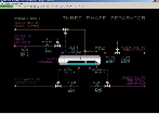
| Click to view schematic display A | Click to view schematic display B |
Process Description
Three Phase Separator, D-001
Crude oil from a manifold is brought into one end of the Three Phase Separator, D-001 and enters the upper section of the vessel which contains a baffle to minimize the disturbances from slugs of oil and water entering with the feed. Oil, water and gas in the feed flow under this baffle into the main separation compartment of the Three Phase Separator. The feed rate is controlled by FIC-001. The design feed flow is 31.1 MBPD.
Gas flashes and separates into the vapor space at the top of the vessel, while immiscible water and oil separate by gravity and form two liquid layers in the separation compartment. The separation compartment is bounded by another baffle extending from the bottom of the vessel to halfway between the top and bottom of the vessel. Separated water and oil collect on the feed side of this baffle. The water/oil interface level is controlled at halfway up the separation baffle (which, therefore, is one quarter of the height of the vessel) by LIC-002 which adjusts the takeoff flow of water from the bottom of the separation compartment. The flow of water is indicated on FI-005. The design flow is 2.0 MBPD. The water contains small amounts of oil and is taken offsite to remove the oil before disposal.
Separated crude oil floats on the water phase and accumulates and spills over the separation baffle into the collection compartment of the Three Phase Separator. The level of collected oil in this compartment is controlled by LIC-001 which adjusts the flow of oil taken from this compartment to the 2nd Stage Separator (battery limit). The flow of crude oil is indicated on FI-004. The design flow of produced oil is 16.2 MBPD.
Note that LIC-002 indicates 100% when the water/oil interface level in the separation compartment is at the height of the separation baffle. If the interface level goes higher than 100%, water will flow over the separation baffle and mix with oil on the collection side. In this situation, an additional load of water will be placed on the downstream separator.
The separation of water out of the oil is not complete as it takes a very long residence time in the separation compartment for this to occur and also because there is agitation of the liquid phases due to the high rate of initial gas separation in the Three Phase Separator. Larger droplets of water will coalesce and fall to the bottom of the separation compartment more easily than smaller droplets. Given the residence time of oil and water in the separation compartment, small droplets of water will be contained in the crude oil in the collection compartment. Most of this water will be separated in downstream separators.
Gas that is flashed and desorbed from the crude oil is collected in the vapor space of the Three Phase Separator and flows to the opposite end. The residence time that allows water to separate from the oil also allows entrained gas in the oil to desorb from the oil.
To make sure there are as few droplets of oil and water leaving with the gas, a demisting pad extends from the top of the vessel to the middle of the vessel over the separation compartment. This ensures the vapor must pass through the demisting pad as the level of oil in the separation compartment will be slightly higher than the liquid separation baffle. The demisting pad is made of crinkled wire mesh screen (CWMS). Any entrained droplets of liquid will impact the wires and the droplets will coalesce and drain into the oil phase of the separation compartment.
The pressure in the Three Phase Separator is normally controlled by PIC-004 which regulates the flow of gas leaving the Three Phase Separator to the Gas Compressor (battery limit). A check valve is installed in the line to prevent back flow of gas to D-001.
In the event the pressure in D-001 builds, an automatic vent to the flare system is provided. PIC-005 will open at 1,800 PSIG to avoid over pressuring D-001. Also, D-001 is outfitted with a pressure safety valve (PSV) set at 2,000 PSIG.
Normally, D-001 operates at a pressure of 1,627 PSIG and a temperature of 162 DEG F while producing 35.2 MMSCF/D of gas.
Instrumentation
This section describes the controls and instruments of the Three Phase Separator. Refer to the Process Flow & Instrumentation Diagrams above for details of the connections.
Note that there are no special controls in the Three Phase Separator process. All controllers are single loop configurations.
The flow rate of crude oil feed (battery limit) to the Three Phase Separator D-001 is controlled by FIC-001. The flow is in volumetric units and will depend on the makeup of oil, water and gas in the line. The temperature of the feed at the battery limit is indicated on TI-001.
The oil level of the Three Phase Separator D-001 is controlled by LIC-001 which regulates the control valve on the line to the 2nd Stage Separator (battery limit). The oil flow is indicated on FI-004.
The water/oil interface level of D-001 is controlled by LIC-002. The produced water flow is indicated on FI-005.
The pressure of the gas produced in D-001 is normally controlled by PIC-004 which adjusts the flow of produced gas to the Gas Compressor at battery limits. The temperature of the gas is indicated on TI-004. The produced gas flow from D-001 is indicated on FI-006.
PIC-005 is an emergency vent to flare that will open if the pressure of D-001 rises above 1,800 PSIG. It is designed to open before the pressure safety valve PSV-001 opens (setpoint = 2,000 PSIG). It can also be used to depressure D-001 at shutdown.
Additional instruments (PHH-006 and LHH-003) are part of the interlock logic for D-001.