Process Description
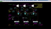
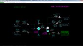
The Advanced Gas Oil Separation Process (GOSP) includes three crude oil production wells, high and low pressure production manifolds, a test manifold, a test separator, and two parallel 3-stage (gas, oil, and water) separation trains.
Crude oil from the wells can be routed to any of the three collection manifolds. Crude oil from the two production manifolds is routed to either of the 3-stage separation trains. Crude oil from the test manifold is routed to the test separator to determine a well’s characteristics before placing the well into production service.
Each separation train consists of three 3-phase separators operating at successively lower pressures to separate the crude oil into oil, gas, and water streams. Gas released from the 2nd and 3rd Stage Separators is compressed and combined with gas from the 1st Stage Separator before being sent to treating. Water from each separator is collected and sent to water treating for disposal.
Crude oil from the High Pressure Production Manifold is routed to the 1st Stage Separator. Flashed gas from the 1st Stage Separator combines with compressed flash gas and sent to treating for water removal. Crude oil from the 1st Stage Separator is sent to the 2nd Stage Separator, along with oil from the Low Pressure Production Manifold.
Flash gas from the 2nd Stage Separator is combined with compressed flash gas from the 1st Stage Separator and the combined gas is cooled and compressed in two successive stages before combining with the flash gas from the 1st Stage Separator. Condensate from cooling the combined gases is separated before compression in a suction knockout drum. Condensate and crude oil from the 2nd Stage Separator is routed to the 3rd Stage Separator.
Flash gas from the 3rd Stage Separator is cooled and compressed in the 1st stage of the Gas Compressor. Condensate from cooling the flash gas is separated before compression in a suction knockout drum. The condensate is returned to the 1st Stage Separator by gravity. Crude oil from the 3rd Stage Separator is sent to storage.
Gas from 2nd stage of the Gas Compressor is cooled and condensate is separated before compression in a suction knockout drum. The condensate is routed to the 2nd Stage Separator.
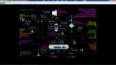
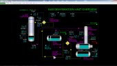
The Gas Dehydration Unit removes water vapor from produced gases destined for pipelines using tri-ethylene glycol (TEG) as the desiccating agent in the process. Removal of water vapor is essential to avoid the formation of slugs of water and hydrates (ice-like solids) in downstream operations. TEG remains completely in the liquid state at the normal operating conditions of the Gas Dehydration process. The so-called wet gas contacts lean, regenerated TEG in the Glycol Contactor, T-601. The rich TEG is then regenerated in the Still Column, T-611, by heating up the TEG with hot oil. The lean TEG is pumped back to Glycol Contactor. Dried gas produced from the Glycol Contactor contains a fraction of the water vapor concentration in the wet gas.
Instrumentation
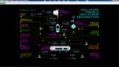
Wells and Manifolds Section
The choke valves on the Wellheads #1, #2 and #3 are manually controlled with HIC-001, HIC-002 and HIC-003, respectively. The emergency shutdown valves are under control of the interlocks associated with each well (see section on interlocks). Each well is lined up to one of the three manifolds using switches. Well #1 uses switches HS-001A, HS-001B and HS-001C. The switches for Wells #2 and #3 are similarly tagged to the well number. The flow from each well should only be lined up to one of the manifolds at a time. The control system will not prevent lining up a well to more than one manifold.
The pressure indicators at each of the Wellheads allow the operator to determine if a well’s pressure is declining or if there is too much flow through the choke valve. Wellhead pressures are normally above 4,000 PSIG, but can be higher or lower depending on the associated well and reservoir characteristics and age.
The two production manifolds each have two hand controllers to line up flow to the A and the B Separation Trains:
- HIC-004A routes oil from the HP Production Manifold to 1st Stage Separator, D-101A
- HIC-004B routes oil from the HP Production Manifold to 1st Stage Separator, D-101B
- HIC-005A routes oil from the LP Production Manifold to 2nd Stage Separator, D-201A
- HIC-005B routes oil from the LP Production Manifold to 2nd Stage Separator, D-201B
The flow of oil from the Test Manifold to the Test Separator can be finely adjusted using HIC-006 in conjunction with the choke valve on the well being tested.
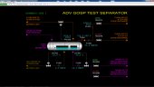
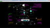
Test Separator Section
The oil level of the Test Separator D-001 is controlled by LIC-001. The destination of the oil is determined by using switches HS-008A and HS-008B. HS-008A lines up oil to the 2nd Stage Separator D-201A while HS-008B lines up oil to the 3rd Stage Separator D-301A. The oil flow is indicated on FI-004.
The water/oil interface level of D-001 is controlled by LIC-002. The produced water flow is indicated on FI-005.
The pressure of the gas produced in D-001 is indicated on PI-004 and its temperature is indicated on TI-004. Gas can be lined up to the 3rd Stage discharge line of Gas Compressor K-101A using HS-007A or to the 1st Stage discharge line of K-101A (E-201A inlet) using HS-007B. The produced gas flow from D-001 is indicated on FI-006.
PIC-005 is an emergency vent to flare that will open if the pressure of the Test Separator rises above 1,800 PSIG. It is designed to open before the pressure safety valve PSV-001 opens (setpoint = 2,000 PSIG). It can also be used to depressure the Test Separator at shutdown.
Additional instruments (PHH-005 and LHH-002) are part of the interlock logic for the Test Separator. See the interlock section for their usage.
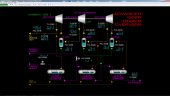
A Train 1st Stage Separator Section
The produced oil level of the 1st Stage Separator D-101A is controlled by LIC-101A. Oil flow is indicated on FI-104A.
The water/oil interface level of D-101A is controlled by LIC-103A. The produced water flow is indicated on FI-105A.
PIC-104A is an emergency vent to flare that will open if the pressure of D-101A rises above 1,800 PSIG. It is designed to open before the pressure safety valve PSV-101A opens (setpoint = 2,000 PSIG). It can also be used to depressure the 1st stage separator at shutdown.
The temperature of the 1st Stage Separator vapor is indicated on TI-101A.
Additional instruments (PHH-104A and LHH-103A) are part of the interlock logic for the 1st Stage Separator. See the interlock section for their usage.
A Train 2nd Stage Separator Section
The produced oil level of the 2nd Stage Separator D-201A is controlled by LIC-201A. Oil flow is indicated on FI-204A.
The water/oil interface level of D-201A is controlled by LIC-203A. The produced water flow is indicated on FI-205A.
PIC-201A is an emergency vent to flare that will open if the pressure of D-201A rises above 450 PSIG. It is designed to open before the pressure safety valve PSV-201A opens (setpoint = 490 PSIG). It can also be used to depressure the 2nd Stage Separator at shutdown.
The temperature of the 2nd Stage Separator vapor is indicated on TI-201A.
An additional instrument (LHH-203A) is part of the interlock logic for the 2nd Stage Separator. See the interlock section for its usage.
A Train 3rd Stage Separator Section
The produced oil level of the 3rd Stage Separator D-301A is controlled by LIC-301A. Oil flow is indicated on FI-304A.
The water/oil interface level of D-301A is controlled by LIC-303A. The produced water flow is indicated on FI-305A.
PIC-301A is an emergency vent to flare that will open if the pressure of D-301A rises above 90 PSIG. It is designed to open before the pressure safety valve PSV-301A opens (setpoint = 490 PSIG). It can also be used to depressure the 3rd Stage Separator at shutdown.
The temperature of the 3rd Stage Separator vapor is indicated on TI-301A.
An additional instrument (LHH-303A) is part of the interlock logic for the 3rd Stage Separator.
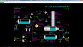
A Train 1st Stage Compression Section
TIC-302A controls the outlet temperature of 1st Stage Suction Cooler E-301A by adjusting the cooling water flow through the 1st Stage Suction Cooler.
The condensate level in the 1st Stage Suction K.O. Drum D-302A is controlled by LIC-302A which controls the flow of condensed liquid to the 3rd Stage Separator D-301A. LHH-302A is a trip sensor for the interlock system of K-101A. The pressure of D-302A is controlled by PIC-302A which adjusts the net flow out of the 1st Stage of Gas Compressor K-101A to the 2nd Stage Suction Cooler E-201A.
FIC-301A is designed to keep a minimum flow through the 1st Stage of the Gas Compressor. At design conditions FIC-301A’s output is 0% because the gas flow is above the minimum. This control keeps the 1st Stage of the Gas Compressor out of surge conditions. Surge can lead to damage of the Gas Compressor as gas rapidly reverses within the compressor, leading to heat-up and excessive vibration. The outlet temperature of the 1st Stage is indicated on TI-303A. THH-303A is the trip sensor for the interlock system of the Gas Compressor. The differential pressure across the 1st Stage of the Gas Compressor is indicated on PDI-301A.
A Train 2nd Stage Compression Section
TIC-202A controls the outlet temperature of the 2nd Stage Suction Cooler E-201A by adjusting the cooling water flow through the 2nd Stage Suction Cooler.
The condensate level in the 2nd Stage Suction K.O. Drum D-202A is controlled by LIC-202A which controls the flow of condensed liquid to the 3rd Stage Separator D-301A. LHH-202A is a trip sensor for the interlock system of K-101A. The pressure of D-202A is indicated on PI-202A.
FIC-201A is designed to keep a minimum flow through the 2nd and 3rd Stages of K-101A. At design conditions FIC-201A's output is 0% because the gas flow is above the minimum. This control keeps K-101A's 2nd and 3rd Stages out of surge conditions. Surge can lead to damage of the Gas Compressor as gas rapidly reverses within the compressor, leading to heat-up and excessive vibration. The outlet temperature of the 2nd Stage is indicated on TI-203A. THH-203A is the trip sensor for the interlock system of K-101A. The differential pressure across the 2nd Stage of K-101A is indicated on PDI-201A.
A Train 3rd Stage Compression Section
TIC-102A controls the outlet temperature of 3rd Stage Suction Cooler E-101A by adjusting the cooling water flow through the 3rd Stage Suction Cooler.
The condensate level in 3rd Stage Suction K.O. Drum D-102A is controlled by LIC-102A which controls the flow of condensed liquid to the 2nd Stage Separator D-201A. LHH-102A is a trip sensor for the interlock system of K-101A. The pressure of D-102A is indicated on PI-102A.
The outlet temperature of the 3rd Stage is indicated on TI-103A. THH-103A is the trip sensor for the interlock system of K-101A. The differential pressure across the 3rd Stage of K-101A is indicated on PDI-101A. HK-101A is a switch to start and stop the motor of the Gas Compressor.
The pressure of the total gas flow produced by flashing and compression is controlled by PIC-101A, which adjusts the flow to the Gas Dehydration Unit. The total gas flow is indicated on FI-101A.
B Train
Controls and Instrumentation of the B Train are identical to the A Train, with the exception of instrument and equipment tags that are suffixed with the letter B instead of A.
Basic Controls: Wet Gas Header
The outlet temperature of Wet Gas Cooler, E-501, is controlled by TIC-501 which adjusts the flow of cooling water through Wet Gas Cooler. Note that the cooling water control valve has a minimum stop setting of 10% in order to guarantee flow always occurs in the Wet Gas Cooler.
PIC-501 controls the pressure of the Wet Gas Header in case it becomes too high by routing cool wet gas to the flare system at battery limits. The setpoint of PIC-501 is normally 1,700 PSIG. PIC-501 is also used at startup before the Gas Dehydration Unit is commissioned.
The level of liquid in Wet Gas Knockout Drum, D-501, is controlled by LIC-501. The flow rate of liquid taken off (mostly light hydrocarbons) is indicated on FI-501.
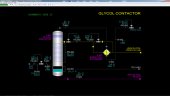
Basic Controls: Glycol Contactor T-601
The flow of the wet gas to the bottom of the Glycol Contactor, T-601, is controlled by FIC-601. However, FIC-601 is normally in manual mode with an output of 100% and takes all the wet gas produced by GOSP trains. If FIC-601 is placed into automatic mode and the flow setpoint is reduced, the Wet Gas Header pressure will increase and will likely cause PIC-501 to open and vent some of the wet gas to the flare system to control the Wet Gas Header pressure.
AI-601 indicates the water content of the wet gas. Pressure and temperature of the wet gas stream are indicated on PI-601 and TI-601, respectively.
The temperature of the dry gas leaving the top of the Glycol Contactor is indicated on TI-603. The temperature of the gas outlet stream from Gas/Glycol Exchanger is indicated on TI-604. AI-602 indicates the water content of the dried gas. The flow of the dried gas to battery limits is controlled by PIC-602.
The lean TEG circulation flow to the Glycol Contactor is controlled by FIC-602. The pressure drop across the trays of the Glycol Contactor is indicated on PDI-603. The level of rich TEG in the bottom of the Glycol Contactor is controlled by LIC-601.
Basic Controls: Gas/Glycol Exchanger E-601
The temperature of the lean TEG leaving Gas/Glycol Exchanger, E-601, is controlled by TIC-602 which adjusts a flow of lean TEG around the Gas/Glycol Exchanger. Approximately 10% of the total lean TEG flow can be bypassed around the Gas/Glycol Exchanger.
Basic Controls: Still Condenser E-611
The temperature of the rich TEG going from Still Condenser, E-611, to the Flash Separator, D-611, is controlled by TIC-611 which adjusts the position of a three-way valve that bypasses rich TEG around the Still Condenser. Normally, this controller is in manual mode and the valve is lined up with 100% flow to the Still Condenser.
Basic Controls: Flash Separator D-611
The pressure of the Flash Separator is controlled by PIC-611 which does split-range control of the fuel gas and flare valves:
- When PIC-611’s output is 0%, the fuel gas valve is wide open and the flare valve is closed
- When PIC-611’s output is 50%, both valves are closed
- When PIC-611’s output is 100%, the fuel gas valve is closed and the flare valve is fully open.
LIC-611 controls the level of rich TEG in the Flash Separator. LIC-612 controls the level of oil in the side sump of the Flash Separator.
Basic Controls: F-611A/B Glycol Filters
The pressure drop across Glycol Filters, F-611A/B, is indicated on PDI-612. PDI-612 will alarm in case of plugging that causes a high pressure drop across the filters.
Basic Controls: Rich/Lean Exchanger E-612
The temperature of rich TEG from Rich/Lean Exchanger, E-612, is indicated on TI-613. The temperature of lean TEG from Rich/Lean Exchanger is indicated on TI-616.
Basic Controls: Still Column T-611
The temperature of the vapor leaving the top tray of Still Column, T-611, is indicated on TI-612.
The pressure drop across the trays of the Still Column is indicated on PDI-613.
Basic Controls: Still Reboiler E-613
The temperature of the lean TEG in Still Reboiler, E-613, is controlled by TIC-614 which adjusts the setpoint of hot oil flow controller FIC-613.
The level of liquid in the Still Reboiler is indicated on LI-613.
This level should normally be around 78 - 80%. The liquid in the Still Reboiler spills over a baffle at this level. Note that the baffle contains holes at the base to drain the liquid on the heating side of the Still Reboiler to the Glycol Drum when the unit is shut down.
Basic Controls: Glycol Drum D-612
The level of lean TEG in Glycol Drum, D-612, is indicated on LI-614. This level will fluctuate as other levels in the unit are changing, but should return to approximately the same indication when levels stabilize.
The temperature of lean TEG drawn from the Glycol Drum is indicated on TI-615.
Fresh glycol can be added to the Glycol Drum using HIC-611.
Glycol from the Glycol Drum can be sent to storage using HIC-612.
Basic Controls: Glycol Circulation Pumps P-611A/B
The motors of Glycol Circulation Pumps, P-611A/B, are operated by switches HS-611A/B, respectively. If a motor should fail, the switch of the affected switch will stay in the STOP state.