 |
 |
 |
|
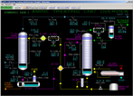
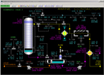
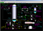
| Click to view schematic display A | Click to view schematic display B | Click to view schematic display C |
Process Description
The Amine Treating Unit removes CO2 and H2S from sour gas and hydrocarbon streams in the Amine Contactor. The Amine (MDEA) is regenerated in the Amine Regenerator, and recycled to the Amine Contactor.
The sour gas streams enter the bottom of the Amine Contactor. The cooled lean amine is trim cooled and enters the top of the contactor column. The sour gas flows upward counter-current to the lean amine solution. An acid-gas-rich-amine solution leaves the bottom of the column at an elevated temperature, due to the exothermic absorption reaction. The sweet gas, after absorption of H2S by the amine solution, flows overhead from the Amine Contactor.
The Rich Amine Surge Drum allows separation of hydrocarbon from the amine solution. Condensed hydrocarbons flow over a weir and are pumped to the drain. The rich amine from the surge drum is pumped to the Lean/Rich Amine Exchanger.
The stripping of H2S and CO2 in the Amine Regenerator regenerates the rich amine solution. The Amine Regenerator Reboiler supplies the necessary heat to strip H2S and CO2 from the rich amine, using steam as the heating medium.
Acid gas, primarily H2S and water vapor from the regenerator is cooled in the Amine Regenerator Overhead Condenser. The mixture of gas and condensed liquid is collected in the Amine Regenerator Overhead Accumulator. The uncondensed gas is sent to Sulfur Recovery.
The Amine Regenerator Reflux Pump, pumps the condensate in the Regenerator Accumulator, mainly water, to the top tray of the Amine Regenerator A portion of the pump discharge is sent to the sour water tank.
Lean amine solution from the Amine Regenerator is cooled in the Lean/Rich Exchanger. A slipstream of rich amine solution passes through a filter to remove particulates and hydrocarbons, and is returned to the suction of the pump. The lean amine is further cooled in the Lean Amine Air Cooler, before entering the Amine Contactor.
Instrumentation
The sour gas stream, 14.5 MMSCFD, enters the bottom of the Amine Contactor at 95 degrees F and 140 psig. The cooled lean amine is trim cooled in exchanger E-103 and enters the top of the absorber column at 105 deg F. The lean amine solution temperature is 10 degrees higher than the feed gas to prevent any hydrocarbon condensation and foaming problems. This temperature differential is maintained by TDIC-103, which allows bypassing of lean amine around the Lean Amine Trim Cooler E-103.
The sour gas flows upward counter-current to the lean amine solution in T-101. An acid-gas-rich-amine solution leaves the bottom of the column at an elevated temperature, 135 deg F, due to the exothermic absorption reaction. The rich MDEA solution temperature is monitored by TI-105. Rich amine leaves the bottom of the column on level control LIC-101 to the Rich Amine Surge Drum D-101.
The sweet gas, after absorption of H2S by the MDEA solution, flows overhead from T-101 under pressure control PIC-101, monitored by the H2S and CO2 analyzers, AI-102 and AI-103. The temperature and flow rate of the gas are monitored with TI-104 and FI-101.
The Rich Amine Surge Drum D-101 allows the amine solution 30 minutes of residence time, which allows separation of hydrocarbon from the amine solution. The drum pressure is maintained by a backpressure controller, PIC-102, at 5 psig. Condensed hydrocarbons flow over a weir and are pumped to the drain system using P-102.
The rich amine from the surge drum is pumped by P-101 to the Lean/Rich Amine Exchanger E-101. The rich amine enters the tube side at 135 deg F, where it is heated to 226 deg F by the hot lean amine solution from the regenerator bottoms. The hot lean amine solution enters the Lean/Rich Exchanger on the shell side at 265 deg F.
The stripping of H2S and CO2 in the Amine Regenerator, T-201, regenerates the rich amine solution. The Amine Regenerator Reboiler supplies the necessary heat to strip H2S from the rich amine, using 60-psig steam as the heating medium.
Acid gas, primarily H2S and water vapor from the regenerator is cooled to 120 deg F in the Amine Regenerator Overhead Condenser. The temperature of the overhead gas is monitored by TI-202 The mixture of gas and condensed liquid is collected in the Amine Regenerator Overhead Accumulator. The pressure is maintained at 16 psig with PIC-201 controlling the acid gas from the Regenerator Accumulator, D-20, to Sulfur Recovery.
The condensate in the Regenerator Accumulator D-201, mainly water, is pumped by the Amine Regenerator Reflux Pump, P-202, to the top tray of the Amine Regenerator. The reflux flow is regulated by level controller LIC-201 and is monitored by FI-203. A part of the pump discharge is sent to the sour water tank.
Lean amine solution from the Amine Regenerator is cooled from 265 degrees F to 189 degrees F in the Lean/Rich Exchanger. A slipstream of rich amine solution is controlled by PDIC-202 through a filter F-201 to remove particulates and hydrocarbons, and returned to the suction of P-201. The lean amine is further cooled in the Lean Amine Air Cooler, E-102, to 130 degrees F.