 |
 |
 |
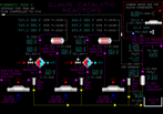
| Click to view schematic display A | Click to view schematic display B | Click to view schematic display C |
 |
 |
|
| Click to view schematic display D | Click to view schematic display E |
Process Description
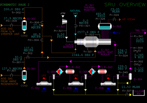
The Sulfur Recovery Unit (SRU) converts H2S in acid gas feeds to elemental liquid sulfur using a 3-stage Claus process. Two feed streams, one from an Amine Regenerator and one from a Sour Water Stripper (SWS), are combusted and reacted with process air in the Thermal Reactor. The Thermal Reactor is designed to destruct NH3 contained in the feed from a Sour Water Stripper by achieving a high temperature in the specially designed burner. Process air is supplied from the Air Blower at a rate that achieves a near-stoichiometric ratio of residual H2S and SO2 in the product tail gas from the SRU.
In the Thermal Reactor the feed H2S is converted to sulfur without the need for catalyst because of the high temperature achieved by the combustion of process air. However, the H2S conversion is limited by reaction equilibrium. High level heat from the Thermal Reactor is recovered in the Waste Heat Boiler by generating high pressure steam. The process gas leaving the Waste Heat Boiler is cooled in Sulfur Condenser No.1 by generating low pressure steam. Liquid sulfur is removed at the outlet of the condenser using a specially designed seal leg and is sent to the Sulfur Storage Pit.
Process gas is reheated in Reheater No. 1 and sent to Catalytic Reactor No. 1 where additional sulfur conversion takes place. The outlet gas from the reactor is cooled in Sulfur Condenser No. 2 and another seal leg removes liquid sulfur. Another reheater, catalytic reactor, and sulfur condenser helps achieve over 95% conversion of the feed H2S to sulfur. The product tailgas from the last sulfur condenser is sent downstream for additional sulfur recovery and/or incineration before discharge to atmosphere.
Instrumentation
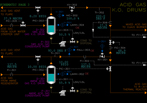
FC-301 controls the acid gas flow from the Amine Regenerator to the Amine Acid Gas K.O. drum by adjusting the inlet control valve. A portion of the amine acid gas is taken off under flow control by FC-304 to the Claus Burner of the Thermal Reactor. The rate of FC-304 is determined by the temperature in the front chamber. If the temperature becomes too low for the destruction of ammonia then the rate is reduced manually. The balance of the amine acid gas is taken off to the back chamber of the Thermal Reactor by the K.O. Drum pressure controller PC-301. In case PC-301 cannot control this pressure PC-302 releases acid gas to the flare system. This can happen if the Claus Unit interlock closes the outlet isolation valve XV-301.
The liquid level of D-301 is indicated on LI-301. A high level alarm condition will cause the Amine Acid Gas Condensate Pump to start and cause the discharge valve to open to drain the drum. Upon reaching a low level alarm condition the pump is stopped and the discharge valve is closed.
FC-305 controls the acid gas flow from the Sour Water Stripper to the SWS Acid Gas K.O. drum by adjusting the inlet control valve. Normally the pressure of D-302 floats on the Thermal Reactor pressure. In case the outlet isolation valve of D-302 is closed PC-303 releases acid gas to the flare system. The position of outlet isolation valve XV-302 can be adjusted using HC-302 as long as the Claus Unit trip interlock is not active.
The liquid level of D-302 is indicated on LI-303. A high level alarm condition will cause the SWS Acid Gas Condensate Pump to start and cause the discharge valve to open to drain the drum. Upon reaching a low level alarm condition the pump is stopped and the discharge valve is closed.
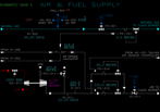
SC-301 controls the speed of the Air Blower by adjusting the flow of medium pressure steam to the turbine. The total flow through the Air Blower is kept constant by FC-311 which blows off discharge air to the atmosphere.
The air flow to the Claus Burner is controlled by two controllers. FC-312 controls the main air. The setpoint of this controller comes from FY-307 which computes the theoretical air demand of all the combustible flows to the Claus Burner. FC-312 has a ratio setting to allow variation of the main air flow setpoint from the theoretical air demand. FC-314 is the second air flow controller. This controller adjusts the trim air flow based on a setpoint from the tail gas controller AC-301.
The natural gas flow to the Claus Burner of the Thermal Reactor is controlled by FC-321. Natural gas is combusted at startup to warm up the SRU equipment and is used to ensure the temperature of the front chamber is high enough to destroy ammonia. Nitrogen is also used at startup to warm up the equipment.
Nitrogen can be added to the process manually using HC-323. Normally, this is used at shutdown so the sulfur can be purged prior to cooling down the unit. The nitrogen valve is automatically opened on a one-shot of HC-323's output in case of a Claus unit trip.
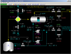
LC-321 controls the level of water in the Steam Drum by adjusting the setpoint of makeup boiler feedwater flow controller FC-323.
The level of the water side of the Sulfur Condensers in controlled by LC-323 which adjusts the setpoint of makeup boiler feedwater flow controller FC-325.
The outlet temperature of Reheater E-303 is controlled by TC-331 which throttles the steam high pressure steam valve. The outlet temperature of Reheater E-305 is controlled by TC-341. A steam trap located on the outlet of each Reheater automatically removes condensate from the heat exchangers.
The tailgas leaving the coalescer is analyzed for the concentration of SO2 and H2S. A special analyzer output signal is created to represent a linear process demand signal for oxygen. The tailgas air demand controller AC-301 uses this signal to attain an approximate 2:1 ratio of residual H2S to SO2 in the tailgas by adjusting the trim air flow to the Claus burner FC-314. Keeping this ratio near the ideal 2:1 stoichiometric ratio ensures the maximum sulfur conversion takes place in the SRU. A setpoint of 0.0 represents a demand for a 2:1 ratio of H2S to SO2. A setpoint less than 0.0 represents a demand for a ratio greater than 2:1. The normal setpoint of AC-301 is -1.0 so that the tailgas air demand is a little less than stoichiometric.