Process Description
A refinery is a manufacturing facility consisting of numerous chemical engineering and unit operation processes which convert and separate raw materials into valuable products having similar properties. These refinery products are recombined (blended) into products that can be used directly by end users. One such common every day example is gasoline for an automobile.
A product like gasoline is, therefore, composed of refinery products blended together in proportions such that the final deliverable product has very specific characteristics. These characteristics can often be achieved by combining any number of refinery products in numerous combinations, all creating a product which satisfies the required properties.
This is where economics and profitability become very important. The overall objective will be to deliver:
- The exact product the end user needs (on-spec product)
- Minimize ‘giveaway’ (for example, don’t provide a product of higher purity than required by contract)
- Deliver this product with the lowest cost combination of raw materials available
Subject to other constraints (such as refinery product availability).
Product quality is characterized by two key properties:
- Anti-Knock Index (AKI), which is measure of gasoline octane.
- Reid Vapor Pressure (RVP), which is a measure of gasoline volatility. Allowable volatility varies based on climate. Summer (warmer) months will require heavier components in the gasoline product to reduce vapor pressure while winter (colder) months can allow for lighter components in the gasoline product.
This dynamic model will help the student familiarize with each of the following:
- Working with automated blending control strategies (albeit a simplified control strategy).
- Switching between automated and manual blending.
- Blending different refinery products to create specific blended products from the Product Blending System.
- Relationships between Refinery Products and specific properties of blended products.
- The economic impact of selecting different refinery products to create a blended product with the desired properties.
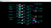
Product blending system
The upstream refinery creates the following products:
- Straight Run Naphtha
- Cracked Naphtha
- Reformate
- Alkylate
- Isomerate
Each of these products are transferred from the refinery to large storage tanks. The storage tanks serve as inventory buffers so that the inventory may allow for fluctuations in the Refinery or the Product Blending System without immediately impacting the other unit.
Refinery Products are pumped from the large storage tanks to either
- Product Distribution Channels (e.g. Tankers, Tanker Trucks, Rail Cars) via Inline Blend Header, H-011.
- Pipeline via Blending Tank, T-009, and Blending Tank Pumps, P-009A/B.
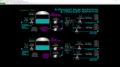
Straight Run Naphtha, Cracked Naphtha
The Straight Run Naphtha Tank, T-002, collects Straight Run Naphtha from the
upstream refinery. Straight Run Naphtha Pumps, P-002A/B, will transfer inventory
from T-002 either to:
- the Inline Blend Header, H-011, or
- the Blending Tank, T-009.
Similarly, the Cracked Naphtha Tank, T-003, collects Cracked Naphtha from the upstream refinery. Cracked Naphtha Pumps, P-003A/B, will transfer inventory from T-003 either to:
- the Inline Blend Header, H-011, or
- the Blending Tank, T-009.
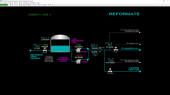
Reformate
The Reformate Tank, T-004, collects Reformate from the upstream refinery.
Reformate Pumps, P-004A/B, will transfer inventory from T-004 either to:
- the Inline Blend Header, H-011, or
- the Blending Tank, T-009.
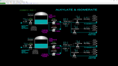
Alkylate, Isomerate
The Alkylate Tank, T-005, collects Alkylate from the upstream refinery. Alkylate
Pumps, P-005A/B, will transfer inventory from T-005 either to:
- the Inline Blend Header, H-011, or
- the Blending Tank, T-009.
Similarly, the Isomerate Tank, T-006, collects Isomerate from the upstream refinery. The Isomerate Pumps, P-006A/B, will transfer inventory from T-006 either to:
- the Inline Blend Header, H-011, or
- the Blending Tank, T-009.
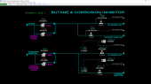
Butane, Corrosion Inhibitor
Butane is transferred to product blending via the Butane Pumps, P-007A/B. Butane is
used to control the Reid Vapor Pressure (RVP) of each of the product streams of the
Product Blending System.
Corrosion inhibitor is transferred to product blending via the Corrosion Inhibitor Pumps, P-008A/B. Corrosion inhibitor is added to the gasoline in small quantities.
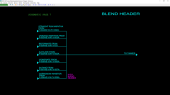
Blend Header
Refinery Product Streams, which are directed to Product Distribution Channels, are
combined in Inline Blend Header, H-011 (Inline Blending), as follows:
- Straight Run Naphtha Tank, T-002, via Straight Run Naphtha Pumps, P-002A/B
- Cracked Naphtha Tank, T-003, via Cracked Naphtha Pumps, P-003A/B
- Reformate Tank, T-004, via Reformate Pumps, P-004A/B
- Alkylate Tank, T-005, via Alkylate Pumps, P-005A/B
- Isomerate Tank, T-006, via Isomerate Pumps, P-006A/B
- Butane via Butane Pumps, P-007A/B
- Corrosion Inhibitor via Corrosion Inhibitor Pumps, P-008A/B
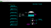
Blend Tank
Refinery Product Streams are directed to the Blending Tank, T-009, as follows:
- Straight Run Naphtha Tank, T-002, via Straight Run Naphtha Pumps, P-002A/B
- Cracked Naphtha Tank, T-003, via Cracked Naphtha Pumps, P-003A/B
- Reformate Tank, T-004, via Reformate Pumps, P-004A/B
- Alkylate Tank, T-005, via Alkylate Pumps, P-005A/B
- Isomerate Tank, T-006, via Isomerate Pumps, P-006A/B
- Butane via Butane Pumps, P-007A/B
- Corrosion Inhibitor via Corrosion Inhibitor Pumps, P-008A/B
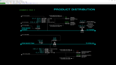
Product Distribution
Blended product is transferred from the Inline Blend Header, H-011, to the Product
Distribution Channels. For SPM-330 delivery to a Marine Tanker is assumed.
Blended product is transferred from the Blending Tank, T-009, to the Pipeline.
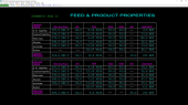
Feed & Product Properties
The schematic includes two tables, one each for
- Distribution Channel product blending, and
- Pipeline product blending.
This schematic summarizes the properties of the refinery products and flow (use) rates for the purposes of creating a blended product. When the properties of refinery products fluctuate (as is normally the case), the controls can be operated manually to create products with specific blend properties. This table is used to identify those components the operator would like to add or remove from the product blend to adjust product properties.
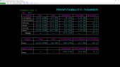
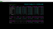
Profitability - Pipeline
The schematic includes three tables which serve as a summary of the profitability for
product delivery to the downstream Product Pipeline.
The cost of each of the components, the usage rate of each component, the spend rate, the total amount used, and the total amount spent on each component for the downstream Product Pipeline is summarized in the Debit Table.
Similarly, the product price, product rate, revenue rate, total product, and total revenue are summarized in the Credit Table.
The Profitability for the Product Pipeline is summarized in the Profit/Loss Table.
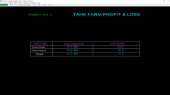
Product Blending Profit & Loss
The schematic is a simple table showing the overall blend production and total
income for the Product Blending System, covering both Product Distribution
Channels (i.e. Tanker) and Pipeline.
Instrumentation
Straight Run Naphtha
FI-102 measures the flow rate of Straight Run Naphtha from the upstream refinery
to the Straight Run Naphtha Tank, T-002. HS-002 will open or close XV-002, the
inlet valve to T-002. The level in T-002 is measured by LAH-002. Should LAH-002
exceed 95%, XV-002 will be forced closed to prevent the tank from overfilling.
There is no other level control associated with this tank.
Straight Run Naphtha is transferred downstream by Straight Run Naphtha Pumps, P-002A/B, using on/off switches, HS-002A and HS-002B, respectively. Only one of these pumps is normally in service. Key properties of the Straight Run Naphtha are measured by AI-002 (90% End Point) and DI-002 (API, which is a measurement representing density). In addition, the properties of Reid Vapor Pressure (RVP), Motor Octane Number (MON), and Research Octane Number (RON) from T-002 are provided on the Feed & Product Properties Schematic (#10).
Straight Run Naphtha flow is controlled by:
- FIC-002A, which receives a setpoint from ratio controller, RIC-002A, for flow to Inline Blend Header, H-011.
- FIC-002B, which receives a setpoint from ratio controller, RIC-002B, for flow to Blending Tank, T-009.
In this control strategy, the key component of the blend is Reformate. RIC-002A is Volumetric Flow of Straight Run Naphtha to Inline Blend Header, H-011/Volumetric Flow of Reformate to Inline Blend Header, H-011. RIC-002B is Volumetric Flow of Straight Run Naphtha to Blending Tank, T-009/Volumetric Flow of Reformate to Blending Tank, T-009.
Cracked Naphtha
FI-103 measures the flow rate of Cracked Naphtha from the upstream refinery to the
Cracked Naphtha Tank, T-003. HS-003 will open or close XV-003, the inlet valve to
T-003. The level in T-003 is measured by LAH-003. Should LAH-003 exceed 95%,
XV-003 will be forced closed to prevent the tank from overfilling. There is no other
level control associated with this tank.
Cracked Naphtha is transferred downstream by Cracked Naphtha Pumps, P-003A/B, using on/off switches, HS-003A and HS-003B, respectively. Only one of these pumps is normally in service. Key properties of the Cracked Naphtha are measured by AI-003 (90% End Point) and DI-003 (API, which is a measurement representing density). In addition, the properties of Reid Vapor Pressure (RVP), Motor Octane Number (MON), and Research Octane Number (RON) from T-003 are provided on the Feed & Product Properties Schematic (#10).
Cracked Naphtha flow is controlled by:
- FIC-003A, which receives a setpoint from RIC-003A for flow to Inline Blend Header, H-011.
- FIC-003B, which receives a setpoint from RIC-003B for flow to Blending Tank, T-009.
RIC-003A is Volumetric Flow of Cracked Naphtha to Inline Blend Header, H-011/Volumetric Flow of Reformate to Inline Blend Header, H-011. RIC-003B is Volumetric Flow of Cracked Naphtha to Blending Tank, T-009/Volumetric Flow of Reformate to Blending Tank, T-009.
Reformate
FI-104 measures the flow rate of Reformate from the upstream refinery to the
Reformate Tank, T-004. HS-004 will open or close XV-004, the inlet valve to T-004.
The level in T-004 is measured by LAH-004. Should LAH-004 exceed 95%, XV-004
will be forced closed to prevent the tank from overfilling. There is no other level
control associated with this tank.
Reformate is transferred downstream by Reformate Pumps, P-004A/B, using on/off switches, HS-004A and HS-004B, respectively. Only one of these pumps is normally in service. Key properties of the Reformate are measured by AI-004 (90% End Point) and DI-004 (API, which is a measurement representing density). In addition, the properties of Reid Vapor Pressure (RVP), Motor Octane Number (MON), and Research Octane Number (RON) from T-004 are provided on the Feed & Product Properties Schematic (#10).
Reformate flow is controlled by:
- FIC-031 for flow to Inline Blend Header, H-011. FI-004A measures the volumetric flow rate of Reformate to Inline Blend Header, H-011.
- FIC-004B, which receives an operator selected setpoint and delivers its flow to Blending Tank, T-009.
These two flow rates of reformate to H-011 and to T-009 are the base flow rates to which the other blending stocks (Straight Run Naphtha, Cracked Naphtha, Alkylate, and Isomerate) will be added at some ratio to these flows. Refer to the controls on Schematic #9 for a description of switches related to automatic and manual setpoint control of these ratios.
Alkylate
FI-105 measures the flow rate of Alkylate from the upstream refinery to the Alkylate
Tank, T-005. HS-005 will open or close XV-005, the inlet valve to T-005. The level in
T-005 is measured by LAH-005. Should LAH-005 exceed 95%, XV-005 will be forced
closed to prevent the tank from overfilling. There is no other level control associated
with this tank.
Alkylate is transferred downstream by Alkylate Pumps, P-005A/B, using on/off switches, HS-005A and HS-005B, respectively. Only one of these pumps is normally in service. Key properties of the Straight Run Naphtha are measured by AI-005 (90% End Point) and DI-005 (API, which is a measurement representing density). In addition, the properties of Reid Vapor Pressure (RVP), Motor Octane Number (MON), and Research Octane Number (RON) from T-004 are provided on the Feed & Product Properties Schematic (#10).
Alkylate flow is controlled by:
- FIC-005A, which receives a setpoint from RIC-005A for flow to Inline Blend Header, H-011.
- FIC-005B, which receives a setpoint from RIC-005B for flow to Blending Tank, T-009.
In this control strategy, the key component of the blend is Reformate. RIC-005A is Volumetric Flow of Alkylate to Inline Blend Header, H-011/Volumetric Flow of Reformate to Inline Blend Header, H-011. RIC-002B is Volumetric Flow of Alkylate to Blending Tank, T-009/Volumetric Flow of Reformate to Blending Tank, T-009.
Isomerate
FI-106 measures the flow rate of Isomerate from the upstream refinery to the
Isomerate Tank, T-006. HS-006 will open or close XV-006, the inlet valve to T-006.
The level in T-006 is measured by LAH-006. Should LAH-006 exceed 95%, XV-006
will be forced closed to prevent the tank from overfilling. There is no other level
control associated with this tank.
Isomerate is transferred downstream by Isomerate Pumps, P-006A/B, using on/off switches, HS-006A and HS-006B, respectively. Only one of these pumps is normally in service. Key properties of Isomerate are measured by AI-006 (90% End Point) and DI-006 (API, which is a measurement representing density). In addition, the properties of Reid Vapor Pressure (RVP), Motor Octane Num (MON) and Research Octane Number (RON) from T-004 are provided on the Feed & Product Properties Schematic (#10).
Isomerate flow is controlled by:
- FIC-006A, which receives a setpoint from RIC-006A for flow to Inline Blend Header, H-011.
- FIC-006B, which receives a setpoint from RIC-006B for flow to Blending Tank, T-009.
RIC-006A is Volumetric Flow of Isomerate to Inline Blend Header, H-011/Volumetric Flow of Reformate to Inline Blend Header, H-011. RIC-006B is Volumetric Flow of Isomerate to Blending Tank, T-009/Volumetric Flow of Reformate to Blending Tank, T-009.
Butane Corrosion Inhibitor
Butane is transferred downstream by Butane Pumps, P-007A/B, using on/off
switches, HS-007A and HS-007B, respectively. Only one of these pumps is normally
in service.
Butane flow is controlled by:
- FIC-007A, which receives a setpoint from AIC-032 for flow to Inline Blend Header, H-011.
- FIC-007B, which receives a setpoint from AIC-022 for flow to Blending Tank, T-009.
AIC-032 (see Schematic #9) measures the Reid Vapor Pressure (RVP) of the Inline Blend product to Product Distribution Channels (i.e. Marine Tanker) and provides the setpoint to FIC-007A when FIC-007A is in cascade mode. AIC-022 (see Schematic #9) measures the RVP of the Blending Tank, T-009, and provides the setpoint to FIC-007B when FIC-007B is in cascade mode.
It must be noted that property adjustments to an Inline Blender will be much faster than the same adjustment to a Blending Tank because a Blending Tank may have a significant inventory associated with it.
Corrosion Inhibitor is transferred downstream by Corrosion Inhibitor Pumps, P-008A/B, using on/off switches, HS-008A and HS-008B, respectively. Only one of these pumps is normally in service.
Corrosion Inhibitor flow is controlled by:
- HIC-008A for flow to Inline Blend Header, H-011. The actual flow rate is measured by FI-008A. RI-008A displays the concentration of Corrosion Inhibitor to Inline Blend Header, H-011, in the Total Distribution Channel Flow measured in parts per million (ppm).
- HIC-008B for flow to Blending Tank, T-009. The actual flow rate is measured by FI-008B. RI-008B displays the concentration of Corrosion Inhibitor in the Total Pipeline Flow (measured in ppm).
Blend Header
Refinery products are combined in the Inline Blend Header, H-011, before delivery to
Product Distribution Channels.
Blend Tank
Refinery products are combined in the Blending Tank, T-009, before delivery to the
Pipeline.
The refinery products pass through XV-009 before entering T-009. Under normal circumstances, XV-009 is opened or closed by HS-009. The level in T-009 is measured by LAH-009. Should LAH-009 exceed 90%, XV-009 will be forced closed to prevent the tank from overfilling. There is no other level control associated with this tank.
Product from T-009 is transferred to the Product Pipeline via the Blending Tank Pumps, P-009A/B. These pumps are started and stopped by HS-009A and HS-009B, respectively. Only one of these pumps is normally in service.
Product Distribution
The Inline Blend Header, H-011, has a total flow controller, FIC-031, which adjusts
FV-031. FV-031 manipulates the Reformate flow to H-011.
HIC-031 is opened or closed by the operator, as needed. Note that when the Tanker (Distribution Channel Vessel) level is 95%, HIC-031 is forced to manual mode and closed. After a 5-minute delay to simulate a tanker leaving the loading station and being replaced by another tanker, LAH-031 (tanker level) will automatically reset to 0%. Transfer of gasoline to the new tanker is initiated by opening HIC-031.
Product properties for H-011 are as follows:
- AI-031 – 90% End Point of Blend Header Product
- AI-033 – Anti-Knock Index (AKI) of Blend Header Product
- DI-031 – API of Blend Header Product
- AIC-032 – Reid Vapor Pressure (RVP) controller; the output of this controller will serve as the setpoint to FIC-007A (which is the butane feed to H-011 when the Product Blending System is in automatic mode).
The outlet flow from the Blending Tank, T-009, has a total flow controller, FIC-021, which adjusts FV-021. FV-021 manipulates the total flow to the Product Pipeline.
Product properties are as follows:
- AI-021 – 90% End Point of Blend Tank Product
- AI-023 – AKI of Blend Tank Product
- DI-021 – API of Blend Tank Product
- AIC-022 – RVP controller; the output of this controller will serve as the setpoint to FIC-007B (butane feed to the T-009, when the Product Blending System is in automatic mode).
This is also where it is possible to switch between automatic and manual product blending.
- For Inline Blending, HS-032 allows the operator to select between automatic and manual blending. HS-031 is the corresponding switch to select between AKI 87 and 93 (regular and premium gasoline).
- For Tank Blending, HS-022 allows the operator to select between automatic and manual blending. HS-021 is the corresponding switch to select between AKI 87 and 93 (regular and premium gasoline).
Automatic Blending Control
When either HS-032 or HS-022 is placed in automatic mode, the following control
actions take place:
- The four connected ratio controllers for the non-reformate blending stocks are locked in automatic mode.
- The setpoints of these four ratio controllers are set according to the Anti-Knock Index (AKI) switch (HS-031 or HS-021). The setpoints cannot be manually adjusted.
- The four slave flow controllers connected to these ratio controllers are locked in cascade mode.
- The related Reid Vapor Pressure (RVP) controller will be locked in automatic mode.
- The setpoint of the RVP controller is set according to the AKI switch (HS-031 or HS-021). The setpoint cannot be manually adjusted.
The forced setpoints for the ratio controllers will normally result in a blended AKI that satisfies the desired AKI according to the AKI switch (either 87 or 93 AKI), assuming the gasoline blending stocks are at their design properties for Research Octane Number (RON) and Motor Octane Number (MON). If the properties of the blending stocks change, the blended AKI may be higher or lower than the target AKI. A higher AKI is a giveaway of valuable blending stocks having higher RON and MON. A lower than target AKI means that the product does not meet AKI specifications and is unsalable.
Manual Blending Control
To adjust the blending manually, place either HS-032 or HS-022 in manual mode.
Then slowly adjust the ratio of the desired ratio controllers to achieve an on-spec
AKI after blending. In general, if AKI is higher than specification, increase the
ratio(s) of the lower RON/MON blending stock(s).If AKI is lower than specification,
decrease the ratio(s) of the lower RON/MON blending stock(s).
Note that there is a logistical element to making blending ratio adjustments, since using too much, or too little, of one or more blending stocks may result in a large mismatch between refinery production and outgoing blending stock flows. When this happens, the blending stock tank levels will change accordingly. If the tank levels become too high, or too low, the strategy of blending will have to be changed accordingly, to keep the production and blending flows balanced over time.