
Process Description
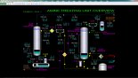
Program SPM-3300 provides an integrated process consisting of the SPM-3100 Amine Treating Unit (ATU) and the SPM-3200 Sulfur Recovery Unit (SRU). This integrated program allows advanced training for coordination of startup and shutdown activities between both units. Such training is essential for minimizing the environmental impact caused by venting sulfur to the atmosphere, which can occur during startup and shutdown transitions.
The ATU removes CO2 and H2S from sour gas and hydrocarbon streams in the Amine Contactor, T-101, using a circulating aqueous amine solvent. The Amine Regenerator, T-201, regenerates amine solvent (MDEA) and recycles it to the Amine Contactor. H2S and CO2 gas from the Amine Regenerator is routed to the SRU for conversion of the H2S into elemental sulfur.
The SRU converts H2S in acid gas feeds to elemental liquid sulfur using a 3-stage Claus process. Two feed streams, one from the Amine Regenerator, and one from a Sour Water Stripper (SWS), combust and react with process air in the Thermal Reactor, R-301. The reacted gas is cooled and condensed sulfur liquid is removed. The remaining gas is reheated and sent to Catalytic Reactor No. 1, R-302, for additional conversion of H2S into sulfur. The gas is cooled again and additional condensed sulfur is removed. The remaining gas is again reheated and reacted in Catalytic Reactor No. 2. The gas is then cooled again, additional condensed sulfur is removed, and the residual Tail Gas is passed to a treating unit (not simulated) to scrub out residual unreacted H2S prior to venting the gas to atmosphere.
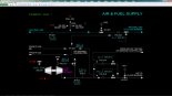
Amine Treating Unit
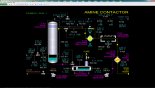
The Amine Treating Unit removes CO2 and H2S from sour gas and hydrocarbon streams in the Amine Contactor, T-101. The amine solvent (MDEA) is regenerated in the Amine Regenerator, T-201, and recycled to the Amine Contactor.
The sour gas streams enter the bottom of the Amine Contactor. The cooled lean amine is trim cooled and enters the top of the contactor column. The sour gas flows upward counter-current to the lean amine solution. An acid-gas-rich-amine solution leaves the bottom of the column at an elevated temperature, due to the exothermic absorption reaction. The sweet gas, after absorption of H2S by the amine solution, flows overhead from the Amine Contactor.
The Rich Amine Surge Drum, D-101, allows separation of hydrocarbon from the amine solution. Condensed hydrocarbons flow over a weir and are pumped to the drain. The rich amine from the surge drum is pumped to the Lean/Rich Amine Exchanger.
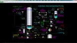
The Amine Regenerator strips H2S and CO2 from the rich amine solution utilizing steam from the Amine Regenerator Reboiler, E-202, as the heating medium.
Acid gas, primarily H2S and water vapor from the regenerator is cooled in the Amine Regenerator Overhead Condenser. The mixture of gas and condensed liquid is collected in the Amine Regenerator Overhead Accumulator. The uncondensed gas is sent to Sulfur Recovery.
The Amine Regenerator Reflux Pump, pumps the condensate in the Regenerator Accumulator, mainly water, to the top tray of the Amine Regenerator A portion of the pump discharge is sent to the sour water tank.
Lean amine solution from the Amine Regenerator is cooled in the Lean/Rich Exchanger. A slipstream of rich amine solution passes through a filter to remove particulates and hydrocarbons, and is returned to the suction of the pump. The lean amine is further cooled in the Lean Amine Air Cooler, before entering the Amine Contactor.
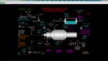
SRU
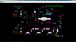
The Sulfur Recovery Unit (SRU) converts H2S in acid gas feeds to elemental liquid sulfur using a 3-stage Claus process. Two feed streams, one from an Amine Regenerator, and one from a Sour Water Stripper (SWS), combust and react with process air in the Thermal Reactor. The Thermal Reactor, R-301, is designed to destruct NH3 contained in the feed from a Sour Water Stripper by achieving a high temperature in the specially designed burner. Process air is supplied from the Air Blower at a rate that achieves a near-stoichiometric ratio of residual H2S and SO2 in the product tail gas from the SRU.
In the Thermal Reactor, the feed H2S is converted to sulfur without the need for catalyst because of the high temperature achieved by the combustion of process air. However, the H2S conversion is limited by reaction equilibrium. High level heat from the Thermal Reactor is recovered in the Waste Heat Boiler by generating high pressure steam. The process gas leaving the Waste Heat Boiler is cooled in Sulfur Condenser No.1, E-302, by generating low pressure steam. Liquid sulfur is removed at the outlet of the condenser using a specially designed seal leg and is sent to the Sulfur Storage Pit.
Process gas is reheated in Reheater No. 1 and sent to Catalytic Reactor No. 1, where additional sulfur conversion takes place. The outlet gas from the reactor is cooled in Sulfur Condenser No. 2 and another seal leg removes liquid sulfur. Another reheater, catalytic reactor, and sulfur condenser helps achieve over 95% conversion of the feed H2S to sulfur. The product tail gas from the last sulfur condenser is sent downstream for additional sulfur recovery and/or incineration before discharge to atmosphere.
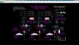
Instrumentation
Basic Controls: Gas Stream
The sour gas stream, 767.6 MSCFH, enters the bottom of the Amine Contactor, T-101, at 95°F and 140 psig. HIC-104 is used to manually adjust the flow rate of the sour gas.
Lean amine is cooled in Lean Amine Trim Cooler, E-103, and enters the top of the Absorber Column at 105°F. The lean amine solution temperature is 10 degrees higher than the feed gas to prevent any hydrocarbon condensation and foaming problems. This temperature differential is maintained by TDIC-103, which allows bypassing of lean amine around the Lean Amine Trim Cooler, E-103.
The sour gas flows upward counter-current to the lean amine solution in Amine Contactor, T-101. An acid-gas-rich-amine solution leaves the bottom of the column at an elevated temperature, 130°F, due to the exothermic absorption reaction. The rich MDEA solution temperature is monitored by TI-105. Rich amine leaves the bottom of the column on level control LIC-101 to the Rich Amine Surge Drum, D-101.
The sweet gas, after absorption of H2S by the MDEA solution, flows overhead from the Amine Contactor under pressure control PIC-101, monitored by the H2S and CO2 analyzers, AI-102 and AI-103. The temperature and flow rate of the gas are monitored with TI-104 and FI-101.
Basic Controls: Amine Solution
The Rich Amine Surge Drum, D-101, allows the amine solution 30 minutes of residence time, which allows separation of hydrocarbon from the amine solution. The drum pressure is maintained by a backpressure controller, PIC-102, at 5.0 psig. Condensed hydrocarbons flow over a weir and are pumped to the drain system using Amine Skim Pump, P-102.
The Rich Amine Pump, P-101, routes rich amine from the Surge Drum to the Lean/Rich Amine Exchanger, E-101. The rich amine enters the tube side at 130°F, where it is heated to 212°F by the hot lean amine solution from the regenerator bottoms. The hot lean amine solution enters the Lean/Rich Amine Exchanger on the shell side at 277°F.
Basic Controls: Regenerator
The flow of hot rich amine from the Lean/Rich Amine Exchanger, E-101, to the top of the Amine Regenerator, T-201, is controlled by FIC-201. The level of regenerated lean amine in the base of the Amine Regenerator is controlled by LIC-203, which adjusts the setpoint of FIC-201.
The Amine Regenerator strips H2S and CO2 from the rich amine solution utilizing 60 psig utility steam as the heating medium. FIC-203 regulates the steam flow to the Amine Regenerator Reboiler, E-202.
Acid gas, primarily H2S and water vapor from the regenerator, is cooled to 93°F in the Amine Regenerator Overhead Condenser. The temperature of the overhead gas is monitored by TI-202. The mixture of gas and condensed liquid is collected in the Amine Regenerator Overhead Accumulator. The pressure is maintained at 16 psig, with PIC-201 controlling the acid gas from the Regenerator Accumulator, D-201, to Sulfur Recovery.
The condensate in the Regenerator Accumulator, which is mainly water, is routed by the Amine Regenerator Reflux Pump, P-202, to the top tray of the Amine Regenerator. The reflux flow is regulated by level controller LIC-201 and is monitored by FI-203. A small part of the pump discharge can be sent to the Sour Water Tank using HIC-202 to maintain the water balance in the ATU, since some water is condensed from the feed sour gas by the circulating amine solution.
Basic Controls: Lean Amine Solution
Lean amine solution from the Amine Regenerator, T-201, is cooled from 277°F to 189°F in the Lean/Rich Exchanger. A slipstream of rich amine solution is controlled by PDIC-202 through Amine Filter, F-201, to remove particulates and hydrocarbons, and returned to the suction of Lean Amine Pump, P-201. The lean amine is further cooled in the Lean Amine Air Cooler, E-102, to 130°F.
Advanced Controls
The lean amine solution temperature is maintained 10°Fhigher than the feed gas to the Amine Contactor, T-101, to prevent any hydrocarbon condensation and foaming. The lean amine solution temperature controller, TIC-102, allows bypassing of lean amine around the Lean Amine Trim Cooler, E-103, and is regulated by TDIC-103 to maintain this 10°Fdifference.