Process Overview
The LNG process takes sweet, desulfurized feedgas and produces liquid natural gas from it. There are 4 main processing steps: chilling and dehydration of the feedgas, separation of the heavier compounds from the feedgas, liquefaction of the feedgas, and removal of nitrogen from the liquefied product.
Additionally there are two closed refrigeration systems to chill the feedgas. These systems are the mixed refrigerant system and the propane refrigeration system.
The feed to the LNG process is mostly methane with additional quantities of nitrogen, ethane, propane, butanes, pentanes, and trace amounts of heavier hydrocarbons. The feed also contains water vapor and trace amounts of methyl mercaptans, other sulfur compounds, and mercury.
Detailed Process Discription
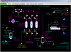
Dehydration
The purpose of the dehydration section is to dry the feedgas from the sweet gas header before liquefaction, remove impurities in the feedgas such as mercaptans and other sulfur compounds to meet product specifications for the LNG product and remove mercury from the feedgas.
Feedgas Chilling
The purpose of the feedgas chilling section is to cool the
feedgas so that heavier hydrocarbons are condensed for removal
downstream in the scrub column, C-521.
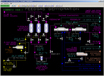
Scrub Column
The purpose of the Scrub Column is to remove heavier hydrocarbons from the feed gas that have condensed in the upstream feedgas chillers, E-511 and E-512. If these are not removed they will freeze and plug up the Main Cryogenic Heat Exchanger, E-532. Fractionation of the feed is employed to minimize the loss of methane in the bottoms product and to minimize the amount of heavier compounds in the net vapor to E-532. The bottoms product from the Scrub Column is taken off to the fractionation section (not simulated) for separation into ethane, propane, butane and C5+.
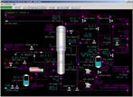
Liquefaction
The purpose of this section is to liquefy the vapor from the Scrub Column reflux drum in the Main Cryogenic Heat Exchanger, E-532 using mixed refrigerant.
The scrubbed process gas enters the middle section of the Main Column Heat Exchanger (MCHE) and finally exits from the top as liquefied natural gas (LNG). Mixed refrigerant (MR) circulates from the MR compressors to the MCHE as both liquid and vapor streams. The MR streams exchange heat within the tube-sides of the MCHE at high pressure and are subsequently depressured through what are termed Joule-Thompson (JT) control valves. The depressurization of the liquid MR causes some vapor to be released from the liquid. In doing so, the temperature of the MR will decrease significantly. This temperature will be lower than the condensation temperature of the largely methane process gas. The depressured MR streams are routed through the shell side of the MCHE to chill the LNG.
As the cold MR on the shell side picks up heat from the process and high pressure MR streams it completely vaporizes and is superheated within the MCHE. The superheated MR is then returned to the Mixed Refrigerant Compressors to complete the cycle.
Mixed refrigerant consists of a mixture of nitrogen, methane, ethane and propane. This mixture is used in the refrigeration cycle because the temperature behavior of the mixture better matches the temperature behavior of the liquefying gas than single-compound refrigerants (e.g. propane) do. As a result the process requires less energy to liquefy the scrubbed gas.
Nitrogen Rejection
This purpose of this section is to remove nitrogen from the LNG produced by the Main Cryogenic Heat Exchanger E-532, pump the LNG to the LNG storage tanks, and compress the nitrogen-rich flash gas and deliver it to the fuel gas system.
Nitrogen is present in the feedgas to the plant and its concentration can vary. In the design condition the sweet gas feed is assumed to contain 6.5% (wt) nitrogen. Nitrogen has no heating value so its presence in the liquid product will decrease the LNG quality. Flashing by depressurization to near-atmospheric pressure removes most of the nitrogen while also auto-chilling the product LNG to storage tank conditions.
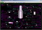
Mixed Refrigerant Compression
The purpose of this section is to compress MR vapors from the MCHE, E-532 so they can be condensed and sent back to the MCHE. Most of the heat to compress and condense the MR is exhausted to the propane refrigeration system. Because of the presence of nitrogen it is not possible to condense all of the MR using propane refrigeration.
The MR vapor and liquid are separated before the MR streams are returned to the MCHE. After separation the vapor MR stream is split into two streams and are liquefied in the MCHE and the Fuel Gas/MR Heat Exchanger prior to being let down in pressure through Joule-Thompson valves that provide the low temperature necessary for liquefying methane in the MCHE.
Propane (C3) Refrigeration System
The purpose of this section is to compress propane vapors from the various propane evaporators so that they can be condensed using cooling water. The three operating pressures in the circulating propane system are the low (LP) which operates at 0.1 bar (g) and -37°C, the medium (MP) which operates at 2.1 bar (g) and -12°C, and the high (HP) which operates at 5.0 bar (g) and 9°C.
After compression and condensing of the propane vapors, the liquid propane refrigerant is accumulated and distributed to the propane evaporators in the plant. The liquid from the accumulator is generally distributed to the HP evaporators first. The shell side of the MR/HP Evaporator E-704 also acts as reservoir of liquid refrigerant for two MP evaporators. As a result, refrigerant is supplied to these MP evaporators at a lower temperature. In the same fashion, two of the MP evaporators act as reservoirs of liquid refrigerant for all four of the LP evaporators.
The vaporized propane from each evaporator is returned to the appropriate propane compressor suction drum. The propane pressure in an evaporator determines the minimum achievable outlet temperature of the evaporator. By using multiple pressure levels the overall efficiency of the refrigeration system is maximized.
Instrumentation
Dehydration
Sweet feedgas at 45°C is brought in from battery limits under flow control by FC-501 at a design rate of 430 tons/hr. The set point of FC-501 is adjusted by PC-502 which controls the pressure at the top of the Scrub Column C-521.
TC-502 controls the feedgas outlet temperature from E-501 by adjusting the set point of pressure controller PC-601. PC-601 controls the pressure of the vaporized refrigerant by adjusting the refrigerant vapor flow back to the HP Compressor Suction Drum, V-603.
The level of refrigerant on shell side of E-501 is controlled by LC-601 which adjusts the flow of liquid refrigerant to E-501. The liquid refrigerant for E-501 is supplied directly from the Propane Accumulator, V-604.
The cooled feedgas from E-501 is passed to V-501 for separation and disposal of the water condensed in E-501. The condensed water is taken offsites for treatment. Two control valves are provided to drain water from V-501 using LC-501A and LC-501B.
The flow of fuel gas is controlled by FC-502 whose output is split between the control valve that supplies fuel gas and the control valve that supplies feedgas to E-502.
The temperature of the regeneration gas is controlled at 285°C by TC-504 which regulates the position of the three-way valve.
Condensate from E-504 is separated from the regeneration gas in V-503. The condensate is removed under level control by LC-502 and sent to the treatment system. Regeneration gas containing small amounts of water vapor, sulfur, and mercury is sent to battery limit by pressure control with PC-504 which keeps the pressure of V-503 at 25.0 bar (g).
Feedgas Chilling
The level of C3 refrigerant is controlled by LC-611 which regulates the flow of refrigerant from E-704. The level of C3 refrigerant is controlled by LC-612 which regulates the flow of refrigerant from E-511.
Scrub Column
Pressure controller PC-521 controls the column pressure by adjusting the feed rate to the dehydration section, FC-501. If more gas flow is drawn through the Main Cryogenic Heat Exchanger the pressure in C-521 will decrease. In response, PC-521 will call for more flow to the unit.
Vapor from the top of the Scrub Column is piped to the warm bundle of the Main Cryogenic Heat Exchanger, E-532, to cool and condense heavy components in the vapor. A bypass line around the warm bundle allows adjustment of the condenser heat duty. This is accomplished by TC-525 which adjusts the bypass flow of vapor around the warm bundle.
The level in the base of C-521 is controlled by LC-522 which adjusts the flow of heavy hydrocarbons to the fractionation section.
The temperature of tray 15 is controlled by TC-521 which normally adjusts the set point of the reboiler's LP steam flow controller FC-521. To avoid a potential freeze-up of the reboiler condensate, an override controller, TC-522, is provided on the bottoms liquid line from the column. The outputs of both TC-521 and TC-522 pass to a high signal selector TY-521 which then sets the set point of the reboiler steam flow controller FC-521.
The Scrub Column Reboiler generates vapor for stripping methane from the liquid flowing down the bottom section of C-521 using low pressure steam. The steam flow is controlled by FC-521.
Condensate from E-521 is collected in V-521. The level of condensate is controlled by LC-521 which controls the flow of condensate to a collection header in the utilities section.
The reflux pumps return condensed hydrocarbons collected in V-522 to tray 1 of the Scrub Column, C-521. Most of the liquid collected in V-522 is returned the tray 1 of the Scrub Column as reflux under control of LC-523/FC-521.
A forward flow controller, FC-524, allows condensed liquid to be injected into the vapor line leaving the Reflux Drum, V-522.
Liquefaction
One of the warm bundles of the MCHE is used as the condenser for the Scrub Column, C-521. The overhead vapor from C-521 is routed to the bundle and is chilled to -51°C. Heavier hydrocarbons are condensed in this bundle and the outlet stream flows to the scrub Column Reflux Drum, V-522.
The second of the warm bundles chills LPG from the LPG Reinjection Cooler, E-531. The LPG from the warm bundle flows to one of the middle bundles for additional chilling. After the middle bundle the LPG is mixed with LNG from control valve PV-531 before entering one of the cold bundles.
Vapor from the Scrub Column Reflux Drum, V-522 and excess Scrub Column reflux enter one of the middle bundles. The vapor completely condenses into LNG at the outlet conditions of 52.0 bar (g) and -120°C. The LNG is then partially depressured across control valve PV-531 to 19.0 bar (g). At this pressure all of the LNG from the middle bundle stays liquid.
After leaving the middle bundle the liquid MR is depressured through FV-733, called the warm JT valve. Depressuring the chilled liquid MR to about 3.5 bar (g) causes the temperature to drop to around -131°C.
The flow of the liquid MR from V-703 is controlled by flow ratio controller FFC-733. The set point of FFC-733 is kept in a desired ratio to the MR vapor flow from V-703.
The flow of HP MR vapor through the MCHE is controlled by pressure ratio controller PPC-775 on the Mixed Refrigerant Compressors. The flow of the MR vapor is adjusted by TC-543 which controls the outlet temperature of the LNG flash vapor from E-533.
C3 refrigerant from E-511 is brought into the shell side of E-531 under control by refrigerant level controller LC-631.
E-533 improves the efficiency of the LNG process by using the cold LNG flash vapor (-159°C) from V-541 to chill and liquefy some of the circulating HP MR vapor to the MCHE. The flow of the MR vapor is adjusted by TC-543 which controls the outlet temperature of the LNG flash vapor from E-533 to -36°C.
Nitrogen Rejection
The set point of the LNG flow rate, FC-541, is adjusted by TC-541. As more LNG flows through the MCHE the process value of TC-541 will tend to increase because the MCHE will not be able to chill the LNG as much at higher throughputs.
PC-541 controls the capacity of the gas through the Fuel Gas Compressor. In case PC-541 cannot control the pressure of V-541 (e.g. a trip of the Fuel Gas Compressor occurs) PC-542 will open and send flash vapor to the flare system.
The liquid LNG in V-541 is taken off to the LNG storage tanks by the LNG Product Pumps, P-541A/B under control by LC-541. If the Fuel Gas Compressor is out of service then the LNG from the MCHE may be routed directly to tank via FC-542. A selector switch allows lining up TC-541 to FC-541 or FC-542.
The net flow through the compressor is controlled by PC-541 on the outlet of the LNG Flash Drum V-541. At normal rates, PC-541 will adjust the opening of the valve on the inlet of the compressor. This valve has a mechanical stop that limits how far the valve can be closed so that the compressor cannot be starved of gas. When this mechanical stop limit is approached, the control system will begin to open the anti-surge valves on both stages of the compressor to reduce the net forward flow of gas to the Fuel Gas System.
Each compressor stage is protected by an anti-surge controller (XC-552 and XC-554) which keeps a sufficient flow of gas through the stage by opening the anti-surge valves. Because it is possible for PC-541 to open the anti-surge valves for capacity control, a high selector function is provided for each valve that chooses between the signal from PC-541 and the signal from the anti-surge controller.
Mixed Refrigerant Compression
LC-674 controls the level of refrigerant on the shell side of E-702. The MR leaves E-702 at 11°C and flows to the MP MR Suction Drum, V-702 at 16.1 bar (g).
An anti-surge controller XC-775 monitors the flow, temperatures and pressures of K-701. Recycle of MR is taken from the outlet of E-701 to V-701 under the control of XC-775.
An anti-surge controller XC-776 monitors the flow, temperatures and pressures of K-702. Recycle of MR is taken from the outlet of E-703 to V-702 under the control of XC-776.
The speed of KT-701 is controlled by SC-771 which adjusts the fuel flow to the gas turbine. During startup the helper motor KM-701 can be used to provide additional power.
The level of propane liquid is controlled by LC-671.C3 vapor is returned to the HP C3 Compressor Suction Drum, V-603.
The level of propane liquid is controlled by LC-672. C3 vapor is returned to the MP C3 Compressor Suction Drum, V-602.
The level of propane liquid is controlled by LC-673. C3 vapor is returned to the LP C3 Compressor Suction Drum, V-601.
Liquid is drawn to the MCHE, E-532 under control of FFC-773 which regulates the warm JT valve of the MCHE. Most of the vapor is drawn through the MCHE under control of PPC-775 which regulates the cold JT valve of the MCHE. PPC-775 controls the overall pressure ratio of the MR compressor. For a given operating speed, controlling the pressure ratio will roughly keep the circulating flow of mixed refrigerant constant.
A second, smaller vapor flow of MR is routed from V-703 to the Fuel Gas/MR Exchanger E-533 to condense the vapor using cold flash gas from the LNG Flash Drum, V541. The flow rate of this vapor is controlled by TC-543 which regulates the LNG flash vapor temperature leaving E-533.
One of the most important operating parameters in the MR system is the ratio of circulating liquid to vapor. This is set on FFC-733 which adjusts the liquid flow through the MCHE to the warm JT valve relative to the circulating vapor flow. Gradual adjustments of this ratio can be made to optimize the temperature differences at the cold, middle and warm ends of the MCHE. Too low a liquid flow will cause the warm end temperature difference to decrease.
Propane (C3) Refrigeration System
Accumulated liquids can be drained to the MR/LP Propane Evaporator, E-706 by gravity. V-601 can be depressured to flare, if needed, using HC-661. The vapor from V-601 flows into the LP stage of the Propane Compressor, K-601.
Accumulated liquids can be drained to the MR/HP Propane Evaporator, E-704 by gravity. The vapor from V-603 flows into the HP stage of the Propane Compressor, K-601. Vapor can also be vented to flare using HC-663.
K-601 is a single-body compressor with multiple stages for compression of propane vapors at three pressures. It is driven by a gas turbine under speed control by SC-661. Each stage of K-601 is provided with an anti-surge valve that recycles desuperheated vapor from the outlet of the Propane Desuperheater, E-601 to the three suction drums. During normal operation the anti-surge controllers, XC-661 and XC-662, close the anti-surge valves since there is a lot of vapor circulating through the compressors. However, when the compressor is started these valves will be fully opened by the anti-surge controllers. Note that XC-662 controls both the MP and the HP anti-surge valves.
Any non-condensables (e.g. nitrogen, methane) present in the system will get trapped in the vapor space of the accumulator. Non-condensables are vented from the top of V-604 to the Propane Reclaimer, C-601. A rise in the pressure indicated at PC-665 (top of C-601) above the equilibrium pressure of propane (determined by the temperature of propane in V-604) indicates that non-condensables are accumulating in V-604.
The Propane Reclaimer minimizes the amount of propane that is lost when venting non-condensables to the LP Mixed Refrigerant Compressor Suction Drum, V-701, via PC-665.