


Process Description
The feed NGL is separated by the following distillation columns:
- Deethanizer T-201
- Depropanizer T-301
- Debutanizer T-401
Feed NGL is preheated in Preheater E-200 using hot natural gasoline from the bottom of Debutanizer.
To effect separation in each distillation column, heat is provided to the respective reboiler by a hot oil system (E-202, E-302 and E-402). The condenser on each column exhausts heat to either propane refrigerant (in the case of the Deethanizer Condenser E-201) or to cooling water (in the case of Depropanizer Condenser E-301 and Debutanizer Condenser E-401). In the case of the Debutanizer, a supplemental reboiler (E-203) for the Deethanizer also serves as a condenser for the Debutanizer. Normally E-203 is in service while E-401 is on standby. The operating pressure of each column depends roughly on the vapor pressure of the overhead product at the cooling medium’s temperature. Propane refrigeration is used for the Deethanizer Condenser in order to keep the operating pressure of the Deethanizer equipment at an economical level.
Each distillation column produces a reasonably pure product from the overhead system of the column. Overhead product from each condenser is collected in the reflux drum (D-201, D-301 and D-401). The bottoms product from the Deethanizer is fed to the Depropanizer and the bottoms product from the Depropanizer is fed to the Debutanizer. The Debutanizer produces a light natural gasoline.
No pumps are required to transport bottoms products from the distillation columns because they operate at successively lower pressures in the processing sequence. The pressure in the last column (Debutanizer) is sufficient to push light natural gasoline to atmospheric product storage. Reflux pumps (P-201A/B, P-301A/B and P-401A/B) are required for each column since the columns’ condensers and reflux drums are located at grade and the reflux must be returned to the top of each distillation column. The reflux pumps also serve to move overhead distillate product to storage.
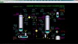
Deethanizer Column and Reboilers
NGL feed is first preheated in Preheater E-200 using hot Debutanizer bottoms product (light gasoline). T-201 consists of 36 distillation trays and the feed is introduced on tray 24 (bottom-most tray is tray 1). The feed liquid is distilled into an ethane product produced in the overhead section of the Deethanizer and a liquid product from the bottom of the column.
Removal of most of the ethane from the bottoms liquid is ensured by heating in Deethanizer Reboiler No. 1, E-202, which uses hot oil as its heating medium. The reboiler takes gravity flow of liquid from a full trap-out pan below tray 1. Much of the heated liquid vaporizes on the shell side of E-202 which is a shell-and-tube heat exchanger. The heated effluent from E-202 returns to the bottom section of T-201 and separates. The hot vapor returns to tray 1 after passing through the vapor chimney of the trap-out pan that feeds the reboiler. The liquid falls into the base of T-201 where it is collected and taken off to the Depropanizer T-301. The bottom liquid contains about 1.6 mole % ethane. Additional reboiler heat is provided in parallel to E-202 by condensing Debutanizer overhead vapor in Deethanizer Reboiler No. 2, E-203. E-203 can be taken out of service if necessary.
Rising warm vapors produced by the reboilers contact cooler feed and serve to vaporize ethane from the feed. Coincidentally, a significant concentration of propane vapors (about 5 mole %) will also rise above the feed tray with the ethane released from the feed. The top section of trays is refluxed with cold overhead liquid from Deethanizer Reflux Pumps P-201A/B to help condense and wash the propane down to the bottom of T-201. Net overhead vapor from the top of T-201 contains about 98 mole % ethane with the balance being mostly methane and very small concentrations of CO2 and propane. The concentration of propane in the product ethane is 0.10 mole %.
PSV-201 is a pressure safety valve that protects T-201 from mechanical damage due to overpressure. Its set pressure is 400 PSIG.
Deethanizer Overhead Section
Most of the vapor from the top of the Deethanizer is condensed in Deethanizer Condenser E-202. The condenser uses liquid propane from battery limits as a refrigerant to chill the overhead vapor down to 19 DEG F. The vaporized refrigerant is returned back to battery limits under pressure control.
A small amount of light gas containing methane, CO2 and some ethane is separated from the condensed liquid in Deethanizer Reflux Drum D-201. The separated gas is sent to the flare system for disposal. In case the pressure of D-201 cannot be controlled, a second automatic pressure vent to flare is provided.
The liquid collected in D-201 is product ethane and is pumped by Deethanizer Reflux Pumps P-201A/B under flow control to the top of T-201 to serve as reflux. The balance is pumped under level control to storage facilities at battery limits. The reflux pumps are electric motor driven pumps and are of the same capacity. Normally, only one pump is in service.
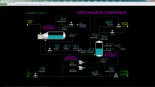
Depropanizer Column and Reboiler
The Depropanizer T-301 receives the net bottoms liquid from the Deethanizer T-201 as feed. T-301 consists of 36 distillation trays and the feed is introduced on tray 24 (bottom-most tray is tray 1). The feed liquid is distilled into a propane product produced in the overhead section of the Depropanizer and a liquid product from the bottom of the column.
Removal of most of the propane from the bottoms liquid is ensured by heating in Depropanizer Reboiler, E-302, which uses hot oil as its heating medium. The reboiler takes gravity flow of liquid from a full trap-out pan below tray 1. Much of the heated liquid vaporizes on the shell side of E-302 which is a shell-and-tube heat exchanger. The heated effluent from E-302 returns to the bottom section of T-301 and separates. The hot vapor returns to tray 1 after passing through the vapor chimney of the trap-out pan that feeds the reboiler. The liquid falls into the base of T-301 where it is collected and taken off to the Debutanizer T-401. The bottom liquid contains about 1.3 mole % propane.
Rising warm vapors produced by the reboiler contact cooler feed and serve to vaporize propane from the feed. Coincidentally, a significant concentration of butane vapors (about 8.5 mole %) will also rise above the feed tray with the propane released from the feed. The top section of trays is refluxed with cold overhead liquid from Depropanizer Reflux Pumps P-301A/B to help condense and wash the butane down to the bottom of T-301. Net overhead vapor from the top of T-301 contains about 97 mole % propane with the balance being mostly ethane from the feed and a small amount of butane. The net concentration of butane in the product propane is 0.10 mole %.
PSV-301 is a pressure safety valve that protects T-301 from mechanical damage due to overpressure. Its set pressure is 350 PSIG.
Depropanizer Overhead Section
All the vapor from the top of the Depropanizer T-301 is condensed in Depropanizer Condenser E-302. The condenser uses cooling water from battery limits to cool and condense the overhead vapor down to 88 DEG F.
The condensed liquid from E-301 enters the bottom of Depropanizer Reflux Drum D-301. The elevation of E-301 relative to D-301 is such that the condensate it produces will form a liquid seal between the shell-side inlet of E-301 and the vapor space of D-301. The liquid level within E-301 will change until the condensing rate matches the overhead vapor flow rate from T-301. Increasing the pressure in D-301 will back up liquid in E-301 which, in turn, will cause a lower condensing rate in E-301. Because of the lower condensing rate, the pressure builds in T-301 until it can push the liquid level in E-301 lower to increase the condensing rate until it balances with the overhead vapor rate from T-301. Therefore, changing the pressure of D-301 will change the pressure of T-301.
In order to increase the pressure of D-301, a hot vapor bypass line is provided around E-302 to admit hot vapor from the overhead of T-301 directly to the vapor space of D-301. To decrease the pressure of D-301, some of the vapor from D-301 is vented to flare. A split-range control loop is used to automatically control the hot vapor bypass and flare control valves. In case the pressure of D-301 cannot be controlled, a second automatic pressure vent to flare is provided.
The liquid collected in D-301 is product propane and is pumped by Depropanizer Reflux Pumps P-301A/B under flow control to the top of T-301 to serve as reflux. The balance is pumped under level control to storage facilities at battery limits. The reflux pumps are electric motor driven pumps and are of the same capacity. Normally, only one pump is in service.
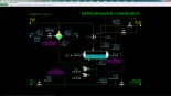
Debutanizer Column and Reboiler
The Debutanizer T-401 receives the net bottoms liquid from the Depropanizer T-301 as feed. T-401 consists of 36 distillation trays and the feed is introduced on tray 24 (bottom-most tray is tray 1). The feed liquid is distilled into a butane product produced in the overhead section of the Debutanizer and a liquid product from the bottom of the column.
Removal of most of the butane from the bottoms liquid is ensured by heating in Debutanizer Reboiler, E-402, which uses hot oil as its heating medium. The reboiler takes gravity flow of liquid from a full trap-out pan below tray 1. Much of the heated liquid vaporizes on the shell side of E-402 which is a shell-and-tube heat exchanger. The heated effluent from E-402 returns to the bottom section of T-401 and separates.
The hot vapor returns to tray 1 after passing through the vapor chimney of the trap-out pan that feeds the reboiler. The liquid falls into the base of T-401 where it is collected and taken off to cooling and storage. The bottom liquid contains about 1.1 mole % butane.
Hot gasoline from the base of T-401 is first cooled in Preheater E-200 by preheating NGL feed to the Deethanizer T-201. The cooled gasoline is then sent through Debutanizer Bottoms Cooler E-403 which uses cooling water from battery limits. In normal operation, the cooled gasoline from E-200 is lower than the cooling water supply temperature, so that the product gasoline warms up a little in E-403. E-403 ensures that only cool gasoline will be sent to storage in case E-200 fouls or is taken out of service.
Rising warm vapors produced by the reboiler contact cooler feed and serve to vaporize butane from the feed. Coincidentally, a significant concentration of pentane vapors (about 11.0 mole %) will also rise above the feed tray with the butane released from the feed. The top section of trays is refluxed with cold overhead liquid from Debutanizer Reflux Pumps P-401A/B to help condense and wash the pentane down to the bottom of T-401. Net overhead vapor from the top of T-401 contains about 97 mole % butane with the balance being mostly propane from the feed and a small amount of pentane. The net concentration of pentane in the product propane is 0.72 mole %.
PSV-401 is a pressure safety valve that protects T-401 from mechanical damage due to overpressure. Its set pressure is 200 PSIG.
Debutanizer Overhead Section
All the vapor from the top of the Debutanizer T-401 is normally condensed in Deethanizer Reboiler No. 2, E-203. The reboiler condenses the overhead vapor down to 166 DEG F. Alternatively, the overhead vapor can be condensed in E-401 using cooling water from battery limits.
The condensed liquid from either E-203 or E-401 enters the bottom of Debutanizer Reflux Drum D-401. The elevations of E-203 and E-401 relative to D-401 is such that the condensate it produces will form a liquid seal between the shell-side inlet of either heat exchanger and the vapor space of D-301. The liquid level within E-203 or E-401 will change until the condensing rate matches the overhead vapor flow rate from T-401. Increasing the pressure in D-401 will back up liquid in E-302 or E-401 which, in turn, will cause a lower condensing rate in the heat exchangers. Because of the lower condensing rate, the pressure builds in T-401 until it can push the liquid level in either heat exchanger to increase the condensing rate until it balances with the overhead vapor rate from T-401. Therefore, changing the pressure of D-401 will change the pressure of T-401.
In order to increase the pressure of D-401, a hot vapor bypass line is provided around E-203/E-401 to admit hot vapor from the overhead of T-401 directly to the vapor space of D-401. To decrease the pressure of D-401, some of the vapor from D-401 is vented to flare. A split-range control loop is used to automatically control the hot vapor bypass and flare control valves. In case the pressure of D-401 cannot be controlled, a second automatic pressure vent to flare is provided.
Note that use of E-203 as the condenser requires operating the Debutanizer at a higher pressure than if using E-401 as the condenser. This is because the temperature at the bottom of Deethanizer T-201 is much higher than the temperature of cooling water supply. The higher pressure ensures that all vapor is completely condensed at the outlet. If this does not occur, the pressures in the system will begin to rise and excessive gas will be continuously sent to flare by the split-range pressure control strategy.
The liquid collected in D-401 is product butane and is pumped by Debutanizer Reflux Pumps P-401A/B under flow control to the top of T-401 to serve as reflux. The balance is pumped under level control through Butane Cooler, E-404, before being sent to storage facilities at battery limits. The reflux pumps are electric motor driven pumps and are of the same capacity. Normally, only one pump is in service. E-404 uses cooling water to cool the product butane.
Instrumentation
Deethanizer Column and Reboiler Controls
The temperature of NGL feed from battery limits is indicated on TI-201. The NGL feed flow is controlled by FIC-201 which adjusts the position of control valve FV-201. The NGL temperature leaving Feed Preheater E-200 is indicated on TI-202. The temperature of Debutanizer bottoms leaving E-200 is indicated on TI-415.
The pressure at the top of Deethanizer T-201 is indicated on PI-203. A second independent pressure indicator, PAH-203, is used as a trip sensor for the Deethanizer Reboiler Interlock I-201. The temperature of vapor leaving the top of T-201 is indicated on TI-203.
TI-204, TI-205, TI-206 and TI-207 indicate the temperatures of trays 32, 28, 18 and 12 of T-201, respectively. TIC-208 controls the temperature of tray 6 by adjustment of the setpoint of hot oil flow controller FIC-002. The temperature of tray 1 liquid to the Deethanizer reboilers is indicated on TI-209. The temperature of the NGL leaving Reboiler No. 1, E-202, is indicated on TI-210. The temperature of T-201 bottoms is indicated on TI-211.
The pressure of the hot oil supply is indicated on PI-001. The temperature of the hot oil supply is indicated on TI-001. The flow of hot oil to E-202 is controlled by FIC-002 which adjusts the position of FV-002. The temperature of hot oil leaving E-202 is indicated on TI-002. If the Deethanizer Reboiler Interlock I-201 is active, FIC-002 will be locked in manual with an output of 0% to prevent flow of hot oil to E-202.
HIC-203 controls the position of the HV-203 to control the flow of tray 1 liquid sent to Reboiler No. 2, E-203. This is normally 72% open. At 100% opening, HV-203 will divert roughly half of the total flow of tray 1 liquid to E-203. The balance will always flow to E-202. The temperature of NGL leaving E-203 is indicated on TI-215. The temperature of condensed T-401 vapor leaving E-203 is indicated on TI-414.
The pressure drop across the top section of T-201 is indicated on PDI-201. The pressure drop across the lower section of T-201 is indicated on PDI-202.
The level of liquid in the bottom of T-201 is controlled by LIC-211 which adjusts the setpoint of bottoms flow controller FIC-211. FIC-211 controls the bottoms flow from T-201 to T-301 by adjustment of the position of FV-211. The ethane content of the bottoms from T-201 is indicated on AI-211.
Deethanizer Overhead Section Controls
The outlet temperature from Deethanizer Condenser E-201 is controlled by TIC-212 which adjusts the setpoint of the refrigerant-side pressure controller PIC-012. PIC-012 controls the refrigerant-side pressure by adjusting the position of PV-012 which returns refrigerant vapor to the refrigeration system at battery limits. The temperature of the refrigerant vapor leaving E-201 is indicated on TI-012. The amount of heat transferred in E-201 depends on the refrigerant-side temperature which directly depends on the pressure at which the refrigerant is boiling.
The level of liquid refrigerant in E-201 is controlled by LIC-011 which adjusts the position of LV-011. When LIC-011 indicates 50%, all the tubes of E-201 are covered with refrigerant. The flow of liquid refrigerant through LV-011 is indicated on FI-011. The temperature of the refrigerant supply is indicated on TI-011 and its pressure is indicated on PI-011.
The level of ethane liquid in Deethanizer Reflux Drum D-201 is controlled by LIC-212 which adjusts the setpoint of product ethane flow controller FIC-214. An independent level is indicated on LAH-212 which is used for the Deethanizer Reboiler Interlock I-201.
The pressure of D-201 is controlled by PIC-212 which adjusts the position of PV-212. The flow of gas through PV-212 to flare is indicated on FI-212. A second independent pressure controller PIC-213 adjusts the position of PV-213. PIC-213 has a setpoint of 400 PSIG and will open PV-213 if PIC-212 is unable to control the pressure of D-201.
The temperature of ethane liquid leaving D-201 is indicated on TI-213. Switches HS-201A and HS-201B are used to change the states of the motors for Deethanizer Reflux Pumps P-201A and P-201B, respectively. The flow of ethane reflux to T-201 is controlled by FIC-213 which adjusts the position of FV-213. The flow of product ethane to storage is controlled by FIC-214 which adjusts the position of FV-214. The concentration of propane in the product ethane is indicated on AI-214.
Depropanizer Column and Reboiler Controls
The temperature of feed to Depropanizer T-301 is indicated on TI-302. The pressure at the top of T-301 is indicated on PI-303. A second independent pressure indicator, PAH-303, is used as a trip sensor for the Depropanizer Reboiler Interlock I-301 (see Interlock I-301 below). The temperature of vapor leaving the top of T-301 is indicated on TI-303.
TI-304, TI-305, TI-306 and TI-307 indicate the temperatures of trays 32, 28,18 and 12 of T-301, respectively. TIC-308 controls the temperature of tray 6 by adjustment of the setpoint of hot oil flow controller FIC-003. The temperature of tray 1 liquid to the Depropanizer Reboiler E-302 is indicated on TI-309. The temperature of the NGL leaving E-302, is indicated on TI-310. The temperature of T-301 bottoms is indicated on TI-311.
The flow of hot oil to E-302 is controlled by FIC-003 which adjusts the position of FV-003. The temperature of hot oil leaving E-302 is indicated on TI-003. If the Depropanizer Reboiler Interlock I-301 is active, FIC-003 will be locked in manual with an output of 0% to prevent flow of hot oil to E-302.
The pressure drop across the top section of T-301 is indicated on PDI-301. The pressure drop across the lower section of T-301 is indicated on PDI-302.
The level of liquid in the bottom of T-301 is controlled by LIC-311 which adjusts the setpoint of bottoms flow controller FIC-311. FIC-311 controls the bottoms flow from T-301 to T-401 by adjustment of the position of FV-311. The propane content of the bottoms from T-301 is indicated on AI-311.
Depropanizer Overhead Section Controls
HIC-023 adjusts the position of Depropanizer Condenser E-301 cooling water supply valve HV-023. The temperature of the cooling water supply is indicated on TI-021 and its pressure is indicated on PI-021. The propane-side outlet temperature from E-301 is indicated on TI-312. The temperature of the cooling water leaving E-301 is indicated on TI-023.
The level of propane liquid in Depropanizer Reflux Drum D-301 is controlled by LIC-312 which adjusts the setpoint of product propane flow controller FIC-314. An independent level is indicated on LAH-312 which is used for the Depropanizer Reboiler Interlock I-301.
The pressure of D-301 is controlled by PIC-312 which adjusts the positions of PV-312A and PV-312B using a split-range calibration. PV-312A is fully open when the output of PIC-312 is 0% and is fully closed at 50%. PV-312A controls the rate hot vapor from T-301 directly to the vapor space of D-301. PV-312B is fully closed when the output of PIC-312 is 50% and is fully open when it is 100%. PV-312B controls the vent flow of D-301's vapor space to flare. The flow of gas through PV-312B to flare is indicated on FI-312. A second independent pressure controller PIC-313 adjusts the position of PV-313. PIC-313 has a setpoint of 320 PSIG and will open PV-313 if PIC-312 is unable to control the pressure of D-301.
The temperature of propane liquid leaving D-301 is indicated on TI-313. Switches HS-301A and HS-301B are used to change the states of the motors for Depropanizer Reflux Pumps P-301A and P-301B, respectively. The flow of propane reflux to T-301 is controlled by FIC-313 which adjusts the position of FV-313. The flow of product propane to storage is controlled by FIC-314 which adjusts the position of FV-314. The concentration of butane in the product propane is indicated on AI-314.
Debutanizer Column and Reboiler Controls
The temperature of feed to Debutanizer T-401 is indicated on TI-402. The pressure at the top of T-401 is indicated on PI-403. A second independent pressure indicator, PAH-403, is used as a trip sensor for the Debutanizer Reboiler Interlock I-401 (see Interlock I-401 below). The temperature of vapor leaving the top of T-401 is indicated on TI-403.
TI-404, TI-405, TI-406 and TI-407 indicate the temperatures of trays 32, 28, 18 and 12 of T-401, respectively. TIC-408 controls the temperature of tray 6 by adjustment of the setpoint of hot oil flow controller FIC-004. The temperature of tray 1 liquid to the Debutanizer Reboiler E-402 is indicated on TI-409. The temperature of the NGL leaving E-402, is indicated on TI-410. The temperature of T-401 bottoms is indicated on TI-411.
The flow of hot oil to E-402 is controlled by FIC-004 which adjusts the position of FV-004. The temperature of hot oil leaving E-402 is indicated on TI-004. If the Debutanizer Reboiler Interlock I-401 is active, FIC-004 will be locked in manual with an output of 0% to prevent flow of hot oil to E-402.
The pressure drop across the top section of T-401 is indicated on PDI-401. The pressure drop across the lower section of T-401 is indicated on PDI-402.
The level of liquid in the bottom of T-401 is controlled by LIC-411 which adjusts the setpoint of bottoms flow controller FIC-411. FIC-411 controls the Debutanizer bottoms flow to storage by adjustment of the position of FV-411. The butane content of the bottoms from T-401 is indicated on AI-411.
Hot Debutanizer bottoms is cooled by exchanging heat with feed NGL in Feed Preheater E-200. Hot Debutanizer bottoms is routed to E-200 by HIC-415 which adjusts the position of 3-way valve HV-415. When HIC-415 is 100%, all the hot bottoms is routed to E-200.
The temperature of the bottoms into Debutanizer Bottoms Cooler E-403 is indicated on TI-416. HIC-025 adjusts the position of E-403 cooling water supply valve HV-025. The temperature of bottoms leaving E-403 is indicated on TI-417. The temperature of cooling water leaving E-403 is indicated on TI-025.
Debutanizer Overhead Section Controls
HIC-412 adjusts the position of 3-way valve HV-412. When HIC-412 is 100%, HV-412 is completely ported to Deethanizer Reboiler No. 2 E-203 to condense the Debutanizer overhead vapor stream. When HIC-412 is 0%, HV-412 is completely ported to Debutanizer Condenser E-401. Normally, HIC-412 is 100% so that the heat from the Debutanizer overhead vapor is used to help reboil the Deethanizer in E-203.
HIC-024 adjusts the position of Debutanizer Condenser E-401 cooling water supply valve HV-024. The butane-side outlet temperature from E-401 is indicated on TI-412. The temperature of the cooling water leaving E-401 is indicated on TI-024.
The level of butane liquid in Debutanizer Reflux Drum D-401 is controlled by LIC-412 which adjusts the setpoint of product butane flow controller FIC-414. An independent level is indicated on LAH-412 which is used for the Debutanizer Reboiler Interlock I-401.
The pressure of D-401 is controlled by PIC-412 which adjusts the positions of PV-412A and PV-412B using a split-range calibration. PV-412A is fully open when the output of PIC-412 is 0% and is fully closed at 50%. PV-412A controls the rate hot vapor from T-401 directly to the vapor space of D-401. PV-412B is fully closed when the output of PIC-412 is 50% and is fully open when it is 100%. PV-412B controls the vent flow of D-401's vapor space to flare. The flow of gas through PV-412B to flare is indicated on FI-412. A second independent pressure controller PIC-413 adjusts the position of PV-413. PIC-413 has a setpoint of 160 PSIG and will open PV-413 if PIC-412 is unable to control the pressure of D-401.
The temperature of propane liquid leaving D-401 is indicated on TI-413. Switches HS-401A and HS-401B are used to change the states of the motors for Debutanizer Reflux Pumps P-401A and P-401B, respectively. The flow of butane reflux to T-401 is controlled by FIC-413 which adjusts the position of FV-413. The flow of product butane to storage is controlled by FIC-414 which adjusts the position of FV-414. The concentration of pentane and higher boiling compounds in the product butane is indicated on AI-414.
HIC-026 adjusts the position of Butane Cooler E-404 cooling water supply valve HV-026. The temperature of butane product leaving E-404 is indicated on TI-418. The temperature of cooling water leaving E-404 is indicated on TI-026.