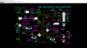
Process Description
The NGL Recovery Unit represents a typical Gas Subcooled Process (GSP) with a turbo-expander. The feed to the unit is gas gathered from wells that has been treated for removal of hydrogen sulfide, water and other detrimental impurities. The feed mainly contains a range of alkane hydrocarbons: methane through octane. Nitrogen and carbon dioxide are also present in small concentrations. The purpose of the NGL recovery unit is to separate out most of the ethane and nearly all of the propane and heavier hydrocarbon compounds from the methane. Nearly all the methane in the feed ends up in the product gas from the unit and is sent to a pipeline along with all the nitrogen in the feed and a fraction of the ethane in the feed. The product gas is termed sales gas. The separated components from the feed are recovered as a liquid product called NGL (natural gas liquids). The NGL is further processed in downstream fractionation units for separation into ethane, propane, butane and light gasoline.
To effect separation, the feed gas is cooled down using:
- cold sales gas from the top of the Demethanizer
- propane refrigerant from battery limit
- auto-chilling by gas expansion and work extraction through an expander (turbine)
- auto-chilling by liquid expansion through valves (auto-refrigeration and Joule-Thomson effects)
As the feed cools down, the heaviest components (propane, butane and light gasoline) condense first. These are separated (warm separation) and sent to the lower part of the Demethanizer. The feed gas is chilled further and some lighter components condense (the balance of the feed propane and most of the ethane). These are separated (cold separation) and sent to the lower part of the Demethanizer along with the warm liquid. A portion of the cold gas is further chilled and condensed using cold Demethanizer overhead gas. The condensed feed gas stream is sent to the top of the Demethanizer to serve as reflux. The balance of the cold gas is further chilled in an expander and the resultant cold stream is sent to the middle-upper part of the Demethanizer. The feed chilling section operates close to the feed gas supply pressure while the Demethanizer overhead operates at a much lower pressure.
The Demethanizer column performs two functions: it strips out most of the dissolved methane in the liquid feeds to the Demethanizer while washing down as much ethane to the bottom. Because the cold temperatures at the top of the column do not allow a sharp separation of these two components, distillation is used to affect their separation, The heavier hydrocarbons will naturally end up in the bottom of the column. Some propane and butane will also tend to rise up the column if there is not enough liquid produced from the Expander and from auto-chilling of liquid feeds to keep the top of the column chilled. Heat is added at the base of the Demethanizer column with a reboiler that uses hot oil as its heat source. This ensures removal of most of the dissolved methane reaching the bottom of the Demethanizer. The NGL collected in the bottom of the Demethanizer is pumped to the NGL Distillation Unit at battery limit.
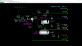
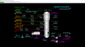
Feed Chilling Warm Section
Treated feed gas at high pressure from battery limits is first cooled in Feed/Sales Gas Exchanger No. 1 E-801 using cool Sales Gas from E-803. The feed gas then passes on to Feed Chiller E-802 which uses propane refrigerant from battery limits. The pressure of vaporized refrigerant on the shell side is controlled to adjust the temperature of the boiling refrigerant which, in turn, controls the outlet temperature of the feed gas from E-802. The vaporized refrigerant is returned back to battery limits.
A portion of the feed gas (approximately 32% of the plant feed rate by weight) is condensed in E-802 and the liquid and vapor are separated in Warm Separator D-801. The collected warm liquid is routed to tray 13 of the Demethanizer T-801. This liquid contains a significant amount of methane which will be stripped out in the lower section of T-801.
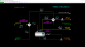
Feed Chilling Cold Section
The vapor stream from D-801 flows through Feed/Sales Gas Exchanger No. 2 E-803 to cool the feed gas further using cold Sales Gas from E-804. Additional liquid is produced from E-803 (approximately 8% of the plant feed rate by weight) and is separated out in Cold Separator D-802.
The cold liquid from D-802 is combined with warm liquid from D-801 and fed to tray 13 of Demethanizer T-801.
A portion of the vapor from D-801 (approximately 24% of the plant feed rate by weight) is further chilled and condensed against Sales Gas directly from the top of Demethanizer T-801 in Feed/Sales Gas Exchanger No. 3 E-804. This stream is depressured to T-801’s pressure across FV-808. The flashing of liquid and the Joule-Thompson effect from depressurization causes the stream temperature to drop. Approximately 33% of the stream, by weight, flashes to vapor. This cold stream, which is rich in methane, is routed to the top of T-801 (tray 40) to provide reflux for washing ethane and propane down the Demethanizer.
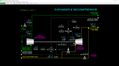
Feed Chilling Expander Section
The balance of vapor from Cold Separator D-802 (about 36% of the plant feed rate by weight) is routed through Feed Gas Expander KT-801. Guide vanes on the inlet of the Expander allow control of the flow rate through the unit. The expander drives the Sales Gas Recompressor K-801 which is an integrated unit.
The Expander/Recompressor normally operate at 10,356 RPM but will dynamically change according to the change in the Expander/Recompressor side conditions. The outlet flow from KT-801 is routed to tray 27 of Demethanizer T-801. Because of both gas expansion and work performed by the expander in turning the Recompressor, the temperature drops across KT-801. Only a small amount of liquid is produced in the outlet of KT-801.
A bypass valve is provided around KT-801 for startup and shutdown operations. Without the Feed Gas Expander in operation, it is difficult to maintain plant capacity and NGL separation. In case of a trip of KT-801, the control system will automatically open the bypass valve on a one-shot basis to a predefined opening that depends on the current feed flow rate.
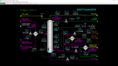
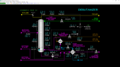
Demethanizer Section
The Demethanizer T-801 is a distillation tower consisting of 40 trays. Its main functions are to strip out any methane from the liquid feeds to the tower and to wash down most of the ethane and all the propane and higher hydrocarbons to the bottom of the column. Cold liquid from E-804 is sent to the top tray (tray 40) to wash down ethane and propane rising with the vapors from the lower sections of the tower. Expander KT-801 outlet is fed to tray 27. Warm liquid from D-801 and cold liquid from D-802 are combined and fed to tray 13.
The top section of T-801 handles most of the uncondensed gas feeding the tower via KT-801. Therefore, the top section of the Demethanizer has a larger diameter than the sections below in order to keep gas velocities through the trays such that flooding (excessive retention of liquid on the trays) does not occur.
Below the bottom most tray of Demethanizer T-801 (tray 1) is a full trap-out pan that routes liquid from tray 1 to the shell side of Demethanizer Reboiler E-805. Hot oil from battery limits is used to heat the liquid to drive off most of the methane that reaches the bottom tray. The vapor from E-805 is returned to the bottom of the Demethanizer and flows through chimney vents in the trap-out pan and then flows up into tray 1. Warm liquid on the shell side of E-805 spills over a weir and flows by gravity into the base of T-801. This liquid bottom is NGL.
NGL in the base of T-801 is pumped by NGL Pumps P-801A/B. These are centrifugal, electric motor-driven pumps. Only one pump is normally in operation. NGL is routed to the Deethanizer tower.
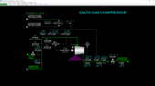
Sales Gas Compression Section
Cold Sales Gas is produced at the top of the Demethanizer and is mainly methane with unrecovered ethane. It also contains almost all the nitrogen contained in feed gas as well as a portion of the carbon dioxide contained in the feed gas. Sales Gas is heated up in the Feed/Sales Gas Heat Exchangers E-804, E-803 and E-801 prior to compression back to pipeline pressure.
The Sales Gas from E-801 is first compressed by the Sales Gas Recompressor K-801 which is driven by the Feed Gas Expander KT-801. K-801 is a centrifugal compressor. A check valve is installed in the bypass line around K-801 to allow Sales Gas flow to continue in case of a trip of KT-801. Because the pressure ratio of K-801 is fairly low, the temperature of the gas leaving K-801 is low enough where it does not have to be cooled prior to final compression in Sales Gas Compressor K-802.
Sales Gas Compressor K-802 is a motor-driven centrifugal compressor and takes suction from the discharge of K-801. The flow through K-802 is adjustable by changing the position of the inlet guide vanes. K-802 discharges into the sales gas pipeline at battery limits. A check valve on the discharge of K-802 prevents back-flow from the pipeline.
At startup and shutdown, the discharge of K-801 can be vented to the flare system.
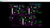
LPG Unit Process Description – Overview
The NGL stream from the bottom of the Demethanizer (T-801) is separated by the following distillation columns:
- Deethanizer T-201
- Depropanizer T-301
- Debutanizer T-401
NGL from the bottom of the Demethanizer is preheated in Preheater E-200 using hot natural gasoline from the bottom of Debutanizer.
To effect separation in each distillation column, heat is provided to the respective reboiler by a hot oil system (E-202, E-302 and E-402). The condenser on each column exhausts heat to either propane refrigerant (in the case of the Deethanizer Condenser E-201) or to cooling water (in the case of Depropanizer Condenser E-301 and Debutanizer Condenser E-401). In the case of the Debutanizer, a supplemental reboiler (E-203) for the Deethanizer also serves as a condenser for the Debutanizer. Normally E-203 is in service while E-401 is on standby. The operating pressure of each column depends roughly on the vapor pressure of the overhead product at the cooling medium’s temperature. Propane refrigeration is used for the Deethanizer Condenser in order to keep the operating pressure of the Deethanizer equipment at an economical level.
Each distillation column produces a reasonably pure product from the overhead system of the column. Overhead product from each condenser is collected in the reflux drum (D-201, D-301 and D-401). The bottoms product from the Deethanizer is fed to the Depropanizer and the bottoms product from the Depropanizer is fed to the Debutanizer. The Debutanizer produces a light natural gasoline.
No pumps are required to transport bottoms products from the distillation columns because they operate at successively lower pressures in the processing sequence. The pressure in the last column (Debutanizer) is sufficient to push light natural gasoline to atmospheric product storage. Reflux pumps (P-201A/B, P-301A/B and P-401A/B) are required for each column since the columns’ condensers and reflux drums are located at grade and the reflux must be returned to the top of each distillation column. The reflux pumps also serve to move overhead distillate product to storage.
Deethanizer Column and Reboilers
The Deethanizer T-201 is a distillation column that receives natural gas liquid (NGL) from the bottom of the Demethanizer.
NGL feed from the Demethanizer is first preheated in Preheater E-200 using hot Debutanizer bottoms product (light gasoline). T-201 consists of 36 distillation trays and the feed is introduced on tray 24 (bottom-most tray is tray 1). The feed liquid is distilled into an ethane product produced in the overhead section of the Deethanizer and a liquid product from the bottom of the column.
Removal of most of the ethane from the bottoms liquid is ensured by heating in Deethanizer Reboiler No. 1, E-202, which uses hot oil as its heating medium. The reboiler takes gravity flow of liquid from a full trap-out pan below tray 1. Much of the heated liquid vaporizes on the shell side of E-202 which is a shell-and-tube heat exchanger. The heated effluent from E-202 returns to the bottom section of T-201 and separates. The hot vapor returns to tray 1 after passing through the vapor chimney of the trap-out pan that feeds the reboiler. The liquid falls into the base of T-201 where it is collected and taken off to the Depropanizer T-301. The bottom liquid contains about 1.6 mole % ethane. Additional reboiler heat is provided in parallel to E-202 by condensing Debutanizer overhead vapor in Deethanizer Reboiler No. 2, E-203. E-203 can be taken out of service if necessary.
Rising warm vapors produced by the reboilers contact cooler feed and serve to vaporize ethane from the feed. Coincidentally, a significant concentration of propane vapors (about 5 mole %) will also rise above the feed tray with the ethane released from the feed. The top section of trays is refluxed with cold overhead liquid from Deethanizer Reflux Pumps P-201A/B to help condense and wash the propane down to the bottom of T-201. Net overhead vapor from the top of T-201 contains about 98 mole % ethane with the balance being mostly methane and very small concentrations of CO2 and propane. The concentration of propane in the product ethane is 0.10 mole %.
PSV-201 is a pressure safety valve that protects T-201 from mechanical damage due to overpressure. Its set pressure is 400 PSIG.
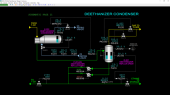
Deethanizer Overhead Section
Most of the vapor from the top of the Deethanizer is condensed in Deethanizer Condenser E-202. The condenser uses liquid propane from battery limits as a refrigerant to chill the overhead vapor down to 19 DEG F. The vaporized refrigerant is returned back to battery limits under pressure control.
A small amount of light gas containing methane, CO2 and some ethane is separated from the condensed liquid in Deethanizer Reflux Drum D-201. The separated gas is sent to the flare system for disposal. In case the pressure of D-201 cannot be controlled, a second automatic pressure vent to flare is provided.
The liquid collected in D-201 is product ethane and is pumped by Deethanizer Reflux Pumps P-201A/B under flow control to the top of T-201 to serve as reflux. The balance is pumped under level control to storage facilities at battery limits. The reflux pumps are electric motor driven pumps and are of the same capacity. Normally, only one pump is in service.
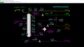
Depropanizer Column and Reboiler
The Depropanizer T-301 receives the net bottoms liquid from the Deethanizer T-201 as feed. T-301 consists of 36 distillation trays and the feed is introduced on tray 24 (bottom-most tray is tray 1). The feed liquid is distilled into a propane product produced in the overhead section of the Depropanizer and a liquid product from the bottom of the column.
Removal of most of the propane from the bottoms liquid is ensured by heating in Depropanizer Reboiler, E-302, which uses hot oil as its heating medium. The reboiler takes gravity flow of liquid from a full trap-out pan below tray 1. Much of the heated liquid vaporizes on the shell side of E-302 which is a shell-and-tube heat exchanger. The heated effluent from E-302 returns to the bottom section of T-301 and separates. The hot vapor returns to tray 1 after passing through the vapor chimney of the trap-out pan that feeds the reboiler. The liquid falls into the base of T-301 where it is collected and taken off to the Debutanizer T-401. The bottom liquid contains about 1.3 mole % propane.
Rising warm vapors produced by the reboiler contact cooler feed and serve to vaporize propane from the feed. Coincidentally, a significant concentration of butane vapors (about 8.5 mole %) will also rise above the feed tray with the propane released from the feed. The top section of trays is refluxed with cold overhead liquid from Depropanizer Reflux Pumps P-301A/B to help condense and wash the butane down to the bottom of T-301. Net overhead vapor from the top of T-301 contains about 97 mole % propane with the balance being mostly ethane from the feed and a small amount of butane. The net concentration of butane in the product propane is 0.10 mole %.
PSV-301 is a pressure safety valve that protects T-301 from mechanical damage due to overpressure. Its set pressure is 350 PSIG.
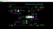
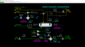
Depropanizer Overhead Section
All the vapor from the top of the Depropanizer T-301 is condensed in Depropanizer Condenser E-302. The condenser uses cooling water from battery limits to cool and condense the overhead vapor down to 88 DEG F.
The condensed liquid from E-301 enters the bottom of Depropanizer Reflux Drum D-301. The elevation of E-301 relative to D-301 is such that the condensate it produces will form a liquid seal between the shell-side inlet of E-301 and the vapor space of D-301. The liquid level within E-301 will change until the condensing rate matches the overhead vapor flow rate from T-301. Increasing the pressure in D-301 will back up liquid in E-301 which, in turn, will cause a lower condensing rate in E-301. Because of the lower condensing rate, the pressure builds in T-301 until it can push the liquid level in E-301 lower to increase the condensing rate until it balances with the overhead vapor rate from T-301. Therefore, changing the pressure of D-301 will change the pressure of T-301.
In order to increase the pressure of D-301, a hot vapor bypass line is provided around E-302 to admit hot vapor from the overhead of T-301 directly to the vapor space of D-301. To decrease the pressure of D-301, some of the vapor from D-301 is vented to flare. A split-range control loop is used to automatically control the hot vapor bypass and flare control valves. In case the pressure of D-301 cannot be controlled, a second automatic pressure vent to flare is provided.
The liquid collected in D-301 is product propane and is pumped by Depropanizer Reflux Pumps P-301A/B under flow control to the top of T-301 to serve as reflux. The balance is pumped under level control to storage facilities at battery limits. The reflux pumps are electric motor driven pumps and are of the same capacity. Normally, only one pump is in service.
Debutanizer Column and Reboiler
The Debutanizer T-401 receives the net bottoms liquid from the Depropanizer T-301 as feed. T-401 consists of 36 distillation trays and the feed is introduced on tray 24 (bottom-most tray is tray 1). The feed liquid is distilled into a butane product produced in the overhead section of the Debutanizer and a liquid product from the bottom of the column.
Removal of most of the butane from the bottoms liquid is ensured by heating in Debutanizer Reboiler, E-402, which uses hot oil as its heating medium. The reboiler takes gravity flow of liquid from a full trap-out pan below tray 1. Much of the heated liquid vaporizes on the shell side of E-402 which is a shell-and-tube heat exchanger. The heated effluent from E-402 returns to the bottom section of T-401 and separates. The hot vapor returns to tray 1 after passing through the vapor chimney of the trap-out pan that feeds the reboiler. The liquid falls into the base of T-401 where it is collected and taken off to cooling and storage. The bottom liquid contains about 1.1 mole % butane.
Hot gasoline from the base of T-401 is first cooled in Preheater E-200 by preheating NGL feed to the Deethanizer T-201. The cooled gasoline is then sent through Debutanizer Bottoms Cooler E-403 which uses cooling water from battery limits. In normal operation, the cooled gasoline from E-200 is lower than the cooling water supply temperature, so that the product gasoline warms up a little in E-403. E-403 ensures that only cool gasoline will be sent to storage in case E-200 fouls or is taken out of service.
Rising warm vapors produced by the reboiler contact cooler feed and serve to vaporize butane from the feed. Coincidentally, a significant concentration of pentane vapors (about 11.0 mole %) will also rise above the feed tray with the butane released from the feed. The top section of trays is refluxed with cold overhead liquid from Debutanizer Reflux Pumps P-401A/B to help condense and wash the pentane down to the bottom of T-401. Net overhead vapor from the top of T-401 contains about 97 mole % butane with the balance being mostly propane from the feed and a small amount of pentane. The net concentration of pentane in the product propane is 0.72 mole %.
PSV-401 is a pressure safety valve that protects T-401 from mechanical damage due to overpressure. Its set pressure is 200 PSIG.
Debutanizer Overhead Section
All the vapor from the top of the Debutanizer T-401 is normally condensed in Deethanizer Reboiler No. 2, E-203. The reboiler condenses the overhead vapor down to 166 DEG F. Alternatively, the overhead vapor can be condensed in E-401 using cooling water from battery limits.
The condensed liquid from either E-203 or E-401 enters the bottom of Debutanizer Reflux Drum D-401. The elevations of E-203 and E-401 relative to D-401 is such that the condensate it produces will form a liquid seal between the shell-side inlet of either heat exchanger and the vapor space of D-301. The liquid level within E-203 or E-401 will change until the condensing rate matches the overhead vapor flow rate from T-401. Increasing the pressure in D-401 will back up liquid in E-302 or E-401 which, in turn, will cause a lower condensing rate in the heat exchangers. Because of the lower condensing rate, the pressure builds in T-401 until it can push the liquid level in either heat exchanger to increase the condensing rate until it balances with the overhead vapor rate from T-401. Therefore, changing the pressure of D-401 will change the pressure of T-401.
In order to increase the pressure of D-401, a hot vapor bypass line is provided around E-203/E-401 to admit hot vapor from the overhead of T-401 directly to the vapor space of D-401. To decrease the pressure of D-401, some of the vapor from D-401 is vented to flare. A split-range control loop is used to automatically control the hot vapor bypass and flare control valves. In case the pressure of D-401 cannot be controlled, a second automatic pressure vent to flare is provided.
Note that use of E-203 as the condenser requires operating the Debutanizer at a higher pressure than if using E-401 as the condenser. This is because the temperature at the bottom of Deethanizer T-201 is much higher than the temperature of cooling water supply. The higher pressure ensures that all vapor is completely condensed at the outlet. If this does not occur, the pressures in the system will begin to rise and excessive gas will be continuously sent to flare by the split-range pressure control strategy.
The liquid collected in D-401 is product butane and is pumped by Debutanizer Reflux Pumps P-401A/B under flow control to the top of T-401 to serve as reflux. The balance is pumped under level control through Butane Cooler, E-404, before being sent to storage facilities at battery limits. The reflux pumps are electric motor driven pumps and are of the same capacity. Normally, only one pump is in service. E-404 uses cooling water to cool the product butane.
Instrumentation
Feed Chilling Warm Section Controls and Instruments
The temperature of feed gas from battery limits is indicated on TI-801 and its pressure is indicated on PI-801. The ethane content of the feed gas is indicated on AI-801. The feed gas flow FIC-801 is normally controlled by adjustment of the Expander inlet guide vane position. Refer to the Advanced Controls section below for more details of the control strategy. HIC-801 is used to adjust the position of feed gas valve HV-801. Normally, HIC-801 is fully open.
TI-802 indicates the outlet temperature of the feed gas from Feed Gas/Sales Gas Exchanger No. 1 E-801. TI-822 indicates the Sales Gas inlet temperature to E-801 and TI-823 indicates the outlet temperature. The pressure of Sales Gas leaving E-801 is indicated on PI-823.
TIC-803 controls the feed gas outlet temperature from Feed Chiller E-802 by adjusting the setpoint of PIC-802 which controls the pressure of the vapor space of the refrigerant side of E-802. In turn, PIC-802 adjusts the position of control valve PV-802 which will affect the flow rate of vaporized refrigerant returned to the Propane (C3) Refrigeration System at battery limits. Changing the pressure of the refrigerant side of E-802 will directly change the temperature at which the propane refrigerant boils in E-802.
LIC-802 controls the refrigerant level in E-802 by adjusting the position of the refrigerant supply valve LV-802. The flow rate of refrigerant through LV-802 is indicated by FI-802.
The two-phase mixture of feed gas leaving E-802 is separated in Warm Separator D-801. The pressure of D-801 is indicated on PI-803. The temperature of feed gas leaving D-801 is indicated on TI-804. The level of liquid in D-801 is controlled by LIC-803 which adjusts the opening of control valve LV-803. The flow of liquid flowing through LV-803 is indicated on FI-803.
Feed Chilling Cold Section Controls and Instruments
The temperature of warm feed gas entering Feed/Sales Gas Exchanger No. 2 E-803 is indicated on TI-804. The temperature of cold feed gas leaving E-803 is indicated on TI-805. The temperature of Sales Gas entering E-803 is indicated on TI-821 and the temperature leaving E-803 is indicated on TI-822.
The two-phase mixture of feed gas leaving E-803 is separated in D-802 Cold Separator. The pressure of D-802 can be controlled by PIC-805 which can be selected to adjust the guide vane position of Sales Gas Compressor K-802. Refer to the Advanced Controls section below for more details of the control strategy.
The flow of feed gas from D-802 to E-804 Feed/Sales Gas Exchanger No. 3 is controlled by FIC-808 which adjusts the position of control valve FV-808 which adjusts the flow of reflux produced by E-804 to the top of T-801. The temperature of reflux leaving E-804 is indicated on TI-806.
The flow of feed gas to KT-801 Expander is indicated on FI-805.
The level of liquid in D-802 is controlled by LIC-806 which adjusts the opening of control valve LV-806. The flow of liquid flowing through LV-806 is indicated on FI-806.
Expander & Recompressor Controls and Instruments
Cold gas from Cold Separator D-802 enters Feed Gas Expander KT-801 by passing through expander trip valve XV-801. XV-801 is controlled by Expander Trip Interlock I-801.
The flow of gas to KT-801 is controlled by the position of the inlet guide vane FV-801A. HIC-801A is a hand controller that is normally in cascade mode and receives its setpoint from selector FY-801.
HIC-801B is a hand controller that adjusts the expander bypass control valve FV-801B. HIC-801B is normally used at startup and shutdown and is automatically adjusted in the event of a trip of KT-801 by I-801 (see section Interlock I-801 below for details). Normally HIC-801B is in manual mode with an output of 0% to close FV-801B. FI-805 indicates the total flow of gas to KT-801 and its bypass.
Switch HS-803 with selector FY-801 form an "A/B switch" used to select the control signal destined for HIC-801A and HIC-801B. Normally HS-803 is in the "A" position to select the output of feed flow controller FIC-801. When it is in the "B" position, it selects the output of Demethanizer overhead pressure controller PIC-814B. The unselected controller of FY-801 is forced into manual mode and its output tracks the selected controller's output. This ensures bump-less control when switching the position of HS-803.
The speed of the shaft connecting Sales Gas Recompressor K-801 and KT-801 is indicated on SI-801. A second speed indication, SAH-801, is used as a trip sensor for interlock I-801. SI-801 will alarm before SAH-801 to give the operator warning of an impending overspeed trip.
The outlet temperature from KT-801 is indicated on TI-807. The mixed gas from KT-801 and its bypass is indicated on TI-812.
XI-801A indicates the status of the machinery monitoring system of the KT-801/K-801 unit. In case of trouble (e.g. excessive vibration, high bearing temperature, low lube oil pressure) XI-801A will produce an alarm. If the trouble is severe, XA-801A will alarm and cause a trip of I-801 to protect the machines.
HS-801 is a switch used to trip and reset interlock I-801. XA-801 generates an alarm that the Expander/Recompressor train has been tripped.
Pi-803 indicates the pressure of Sales Gas entering K-801. TI-824 indicates the discharge temperature of K-801.
PIC-824 controls the discharge pressure of K-801 in the event of a stop of downstream Sales Gas Compressor K-802. PIC-824 controls the position of control valve PV-824 to route gas to the flare system at battery limits.
Demethanizer Controls and Instruments
The flashed reflux feed to the top of Demethanizer T-801 is indicated on TI-811. The cold vapor feed from KT-801 is indicated on TI-812. The flashed combined liquid feeds to T-801 is indicated on TI-813.
The temperature of the overhead vapor leaving the top of T-801 is indicated on TI-814. The temperature of tray 33 in the upper section of T-801 is indicated on TI-815. The temperature of tray 20 in the center section of T-801 is indicated on TI-816. The temperature of tray 7 in the bottom section of T-801 is indicated on TI-817.
The differential pressure across the trays in the upper section of T-801 is indicated on PDI-811. The differential pressure across the trays in the middle section of T-801 is indicated on PDI-812. The differential pressure across the trays in the lower section of T-801 is indicated on PDI-813.
The overhead pressure of T-801 is normally controlled by PIC-814A which adjusts the position of the guide vane on K-802 Sales Gas Compressor. An alternate mode of pressure control is to use PIC-814B to control the inlet guide vane of KT-801 Feed Gas Expander. To avoid unstable control, only one of these two controllers is permitted to be in automatic mode at any time. The advanced control system will reset the second controller that is placed in automatic mode back to manual mode.
The outlet temperature of Reboiler E-805 is controlled by TIC-818 which adjusts the setpoint of the hot oil flow controller FIC-818. The pressure of the hot oil supply is indicated on PI-001 and its temperature is indicated on TI-001. The temperature of the bottoms liquid leaving T-801 is indicated on TI-819.
The level of NGL in the bottom of T-801 is controlled by LIC-819 which adjusts the setpoint of FIC-201 position of LV-819 to regulate the flow of NGL from NGL Pumps P-801A/B to the Deethanizer. The flow of NGL through FV-201 is indicated on FIC-201.
The motors of P-801A/B are operated by switches HS-801A/B, respectively. The methane content in the product NGL is indicated on AI-819.
Sales Gas Compressor Controls and Instruments
TI-824 indicates the Sales Gas temperature from Recompressor K-801. PIC-824 controls the discharge pressure of K-801/suction pressure of Sales Gas Compressor K-802 in the event of a stop of K-802. PIC-824 controls the position of control valve PV-824 to route gas to the flare system at battery limits.
PI-825 indicates the suction pressure of K-802. PI-826 indicates the discharge pressure. The ratio of the two pressures is indicated on PY-826. PYH-826 generates a trip signal for I-802 Sales Gas Compressor interlock based on the PV of PY-826. PY-826 will alarm before the trip point to warn the operator of an impending trip condition.
The discharge temperature of K-802 is indicated on TI-826. A second, independent temperature is indicated on TAH-826 which serves as a trip sensor to I-802. TI-826 will alarm before the trip point of TAH-826 to warn the operator of an impending trip condition.
The flow of Sales Gas from K-802 to the pipeline is indicated on FI-826. The ethane content of the Sales Gas is indicated on AI-826.
HIC-827 is used to isolate K-802 from the pipeline by adjusting the position of control valve HV-827. The pressure of the pipeline is indicated in PI-827.
XI-802A indicates the status of the machinery monitoring system of KT-802. In case of trouble (e.g. excessive vibration, high bearing temperature, low lube oil pressure) XI-802A will produce an alarm. If the trouble is severe, XA-802A will alarm and cause a trip of I-802 to protect the machine.
HS-802A is a switch that operates the electric motor of K-802. HS-802B is a switch used to trip and reset interlock I-802. XA-802 generates an alarm that the Sales Gas Compressor has been tripped. When I-802 is in the trip state, HS-802A is locked in the STOP state.
Switch HS-814 with selector PY-814 form an "A/B switch" used to select the control signal for the inlet guide vane PV-814 of K-802. Normally HS-814 is in the "A" position to select the output of Demethanizer overhead pressure controller PIC-814A. When it is in the "B" position, it selects the output of Cold Separator pressure controller PIC-805. The unselected controller of PY-814 is forced into manual mode and its output tracks the selected controller's output. This ensures bump-less control when switching the position of HS-814.
Interlock I-801
This interlock protects the Expander (KT-801) and Recompressor (K-801) from mechanical damage. It is a latched interlock and is activated by any of the following:
- the speed of the Expander SAH-801 exceeds the trip setting of 15,000 RPM
- mechanical trouble signal XA-801A
- switch HS-801 is manually changed from the OK state to the TRIP state
This interlock has the following effects:
- closes the inlet valve XV-801 to the Expander KT-801
- places HIC-801A (expander guide vane controller) into manual and locks its output to 0.0
- performs a one-time reset of the output of feed flow controller FIC-801 (or PIC-814B) if it is automatic mode. This is done to automatically open the Expander bypass valve to a preset position when the Expander trips. This system minimizes upsets to the unit (see section Special Controls below for other details)
- causes a high alarm on XA-801.
The interlock can be reset after all process trip inputs are cleared by placing switch HS-801 into the OK state.
Interlock I-802
This interlock protects the Sales Gas Compressor (K-802) from mechanical damage. It is a latched interlock and is activated by any of the following:
- the discharge temperature TAH-826 exceeds 302 DEG F for more than 10 seconds
- the pressure ratio PYH-826 exceeds 3.5 for more than 10 seconds
- mechanical trouble signal XA-802A
This interlock has the following effects:
- locks the compressor motor switch HS-802A in the STOP state
- causes a high alarm on XA-802
The interlock can be reset after all trip inputs are cleared by placing switch HS-802B into the OK state. Once the interlock has been reset, K-802 can be started by placing switch HS-802A into the RUN state.
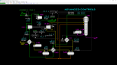
Advanced Controls
This section describes the special controls of the NGL Recovery Unit.
Expander Guide Vane Control
The output signal from feed gas flow controller FIC-801 is connected to the "A" input signal of switch FY-801 which, in turn, is connected to the external setpoint signal of both HIC-801A and HIC-801B which are configured with a ratio of 1.0. Neither HIC will back-initialize any controller when the HIC is not in cascade mode.
An alternate mode of expander guide vane control uses the Demethanizer overhead pressure controller PIC-814B output to the "B" input of FY-801. HS-803 is used to switch between the A and B inputs. To ensure bump-less transfer when switching HS-803, the unselected controller to FY-801 is locked in manual mode and its output tracks the selected controller.
Normally, HS-803 is in the "A" position and feed gas flow controller FIC-801 will control the inlet guide vane position of the Expander while HIC-801A is in cascade mode. The Expander bypass valve will normally be closed with HIC-801B in manual with an output of 0.0. In case the Expander is taken out of service, the bypass valve can be regulated from FIC-801 (or PIC-814B) by placing HIC-801B into cascade mode.
In case of an Expander trip, special logic is required to do a one-shot initialization of controllers FIC-801 (or PIC-814B), HIC-801A and HIC-801B in order to minimize an upset to the unit. This one-shot occurs when:
- FIC-801 (or PIC-814B) is in automatic mode, and
- HIC-801A is in cascade mode, and
- HIC-801B is not in cascade mode, and
- I-801 has just transitioned from OK to TRIP (one-shot)
When this happens, the following takes place:
- FIC-801 (or PIC-814B) is placed in manual for two seconds
- FIC-801 (or PIC-814B) output is initialized to a value calculated from a lookup table that is a function of the feed flow (FIC-801’s PV before the trip) (one-shot)
- HIC-801B is placed into cascade mode (one-shot)
- HIC-801A is locked by interlock I-801 (see above)
- After a delay of three seconds, FIC-801 (or PIC-814B) is placed into automatic mode (one-shot)
- After a delay of four seconds, the setpoint of FIC-801 (or PIC-814B) is restored to the value just before the trip (one-shot)
Sales Gas Compressor Guide Vane Control
The flow of Sales Gas to the pipeline is controlled by adjusting the position of the guide vane on Sales Gas Compressor K-802. The control signal to the guide vane position is selected by switch PY-814 which has Demethanizer overhead pressure controller PIC-814A's output as its "A" input and Cold Separator pressure controller PIC-805's output as its "B" input. The selection of the guide vane control signal is made using hand switch HS-814. To ensure bump-less transfer when switching HS-814, the unselected controller to PY-814 is locked in manual mode and its output tracks the selected controller.
Normally HS-814 is in the "A" position so that PIC-814A controls the guide vane position of the Sales Gas Compressor.
Demethanizer Overhead Pressure Control
There are two controllers, PIC-814A and PIC-814B, for controlling the Demethanizer overhead pressure. Both controllers share the same pressure transmitter. PIC-814A can be used to control the inlet guide vane of the Sales Gas Compressor while PIC-814B can be used to control the inlet guide vane of the Feed Gas Expander. Logic prevents both controllers from being in automatic mode at the same time. The first controller put in automatic mode will remain in automatic mode while the second controller will be set back to manual mode. To switch control, both controllers must first be placed into manual mode.
Deethanizer Column and Reboiler Controls and Instruments
The temperature of NGL feed from Demethanizer Bottoms (via the NGL Pumps) is indicated on TI-201. The NGL feed flow is controlled by FIC-201 whose set point is reset by the Demethanizer Bottoms Level Controller, LIC-819. FIC-201 adjusts the position of control valve FV-201. The NGL temperature leaving Feed Preheater E-200 is indicated on TI-202. The temperature of Debutanizer bottoms leaving E-200 is indicated on TI-415. The pressure at the top of Deethanizer T-201 is indicated on PI-203. A second independent pressure indicator, PAH-203, is used as a trip sensor for the Deethanizer Reboiler Interlock I-201. The temperature of vapor leaving the top of T-201 is indicated on TI-203.
TI-204, TI-205, TI-206 and TI-207 indicate the temperatures of trays 32, 28, 18 and 12 of T-201, respectively. TIC-208 controls the temperature of tray 6 by adjustment of the setpoint of hot oil flow controller FIC-002. The temperature of tray 1 liquid to the Deethanizer reboilers is indicated on TI-209. The temperature of the NGL leaving Reboiler No. 1, E-202, is indicated on TI-210. The temperature of T-201 bottoms is indicated on TI-211.
The pressure of the hot oil supply is indicated on PI-001. The temperature of the hot oil supply is indicated on TI-001. The flow of hot oil to E-202 is controlled by FIC-002 which adjusts the position of FV-002. The temperature of hot oil leaving E-202 is indicated on TI-002. If the Deethanizer Reboiler Interlock I-201 is active, FIC-002 will be locked in manual with an output of 0% to prevent flow of hot oil to E-202.
HIC-203 controls the position of the HV-203 to control the flow of tray 1 liquid sent to Reboiler No. 2, E-203. This is normally 72% open. At 100% opening, HV-203 will divert roughly half of the total flow of tray 1 liquid to E-203. The balance will always flow to E-202. The temperature of NGL leaving E-203 is indicated on TI-215. The temperature of condensed T-401 vapor leaving E-203 is indicated on TI-414.
The pressure drop across the top section of T-201 is indicated on PDI-201. The pressure drop across the lower section of T-201 is indicated on PDI-202.
The level of liquid in the bottom of T-201 is controlled by LIC-211 which adjusts the setpoint of bottoms flow controller FIC-211. FIC-211 controls the bottoms flow from T-201 to T-301 by adjustment of the position of FV-211. The ethane content of the bottoms from T-201 is indicated on AI-211.
Deethanizer Overhead Section Controls and Instruments
The outlet temperature from Deethanizer Condenser E-201 is controlled by TIC-212 which adjusts the setpoint of the refrigerant-side pressure controller PIC-012. PIC-012 controls the refrigerant-side pressure by adjusting the position of PV-012 which returns refrigerant vapor to the refrigeration system at battery limits. The temperature of the refrigerant vapor leaving E-201 is indicated on TI-012. The amount of heat transferred in E-201 depends on the refrigerant-side temperature which directly depends on the pressure at which the refrigerant is boiling.
The level of liquid refrigerant in E-201 is controlled by LIC-011 which adjusts the position of LV-011. When LIC-011 indicates 50%, all the tubes of E-201 are covered with refrigerant. The flow of liquid refrigerant through LV-011 is indicated on FI-011. The temperature of the refrigerant supply is indicated on TI-011 and its pressure is indicated on PI-011.
The level of ethane liquid in Deethanizer Reflux Drum D-201 is controlled by LIC-212 which adjusts the setpoint of product ethane flow controller FIC-214. An independent level is indicated on LAH-212 which is used for the Deethanizer Reboiler Interlock I-201.
The pressure of D-201 is controlled by PIC-212 which adjusts the position of PV-212. The flow of gas through PV-212 to flare is indicated on FI-212. A second independent pressure controller PIC-213 adjusts the position of PV-213. PIC-213 has a setpoint of 400 PSIG and will open PV-213 if PIC-212 is unable to control the pressure of D-201.
The temperature of ethane liquid leaving D-201 is indicated on TI-213. Switches HS-201A and HS-201B are used to change the states of the motors for Deethanizer Reflux Pumps P-201A and P-201B, respectively. The flow of ethane reflux to T-201 is controlled by FIC-213 which adjusts the position of FV-213. The flow of product ethane to storage is controlled by FIC-214 which adjusts the position of FV-214. The concentration of propane in the product ethane is indicated on AI-214.
Depropanizer Column and Reboiler Controls and Instruments
The temperature of feed to Depropanizer T-301 is indicated on TI-302. The pressure at the top of T-301 is indicated on PI-303. A second independent pressure indicator, PAH-303, is used as a trip sensor for the Depropanizer Reboiler Interlock I-301. The temperature of vapor leaving the top of T-301 is indicated on TI-303.
TI-304, TI-305, TI-306 and TI-307 indicate the temperatures of trays 32, 28, 18 and 12 of T-301, respectively. TIC-308 controls the temperature of tray 6 by adjustment of the setpoint of hot oil flow controller FIC-003. The temperature of tray 1 liquid to the Depropanizer Reboiler E-302 is indicated on TI-309. The temperature of the NGL leaving E-302, is indicated on TI-310. The temperature of T-301 bottoms is indicated on TI-311.
The flow of hot oil to E-302 is controlled by FIC-003 which adjusts the position of FV-003. The temperature of hot oil leaving E-302 is indicated on TI-003. If the Depropanizer Reboiler Interlock I-301 is active, FIC-003 will be locked in manual with an output of 0% to prevent flow of hot oil to E-302.
The pressure drop across the top section of T-301 is indicated on PDI-301. The pressure drop across the lower section of T-301 is indicated on PDI-302.
The level of liquid in the bottom of T-301 is controlled by LIC-311 which adjusts the setpoint of bottoms flow controller FIC-311. FIC-311 controls the bottoms flow from T-301 to T-401 by adjustment of the position of FV-311. The propane content of the bottoms from T-301 is indicated on AI-311.
Depropanizer Overhead Section Controls and Instruments
HIC-023 adjusts the position of Depropanizer Condenser E-301 cooling water supply valve HV-023. The temperature of the cooling water supply is indicated on TI-021 and its pressure is indicated on PI-021. The propane-side outlet temperature from E-301 is indicated on TI-312. The temperature of the cooling water leaving E-301 is indicated on TI-023. The level of propane liquid in Depropanizer Reflux Drum D-301 is controlled by LIC-312 which adjusts the setpoint of product propane flow controller FIC-314. An independent level is indicated on LAH-312 which is used for the Depropanizer Reboiler Interlock I-301.
The pressure of D-301 is controlled by PIC-312 which adjusts the positions of PV-312A and PV-312B using a split-range calibration. PV-312A is fully open when the output of PIC-312 is 0% and is fully closed at 50%. PV-312A controls the rate hot vapor from T-301 directly to the vapor space of D-301. PV-312B is fully closed when the output of PIC-312 is 50% and is fully open when it is 100%. PV-312B controls the vent flow of D-301's vapor space to flare. The flow of gas through PV-312B to flare is indicated on FI-312. A second independent pressure controller PIC-313 adjusts the position of PV-313. PIC-313 has a setpoint of 320 PSIG and will open PV-313 if PIC-312 is unable to control the pressure of D-301.
The temperature of propane liquid leaving D-301 is indicated on TI-313. Switches HS-301A and HS-301B are used to change the states of the motors for Depropanizer Reflux Pumps P-301A and P-301B, respectively. The flow of propane reflux to T-301 is controlled by FIC-313 which adjusts the position of FV-313. The flow of product propane to storage is controlled by FIC-314 which adjusts the position of FV-314. The concentration of butane in the product propane is indicated on AI-314.
Debutanizer Column and Reboiler Controls and Instruments
The temperature of feed to Debutanizer T-401 is indicated on TI-402. The pressure at the top of T-401 is indicated on PI-403. A second independent pressure indicator, PAH-403, is used as a trip sensor for the Debutanizer Reboiler Interlock I-401. The temperature of vapor leaving the top of T-401 is indicated on TI-403.
TI-404, TI-405, TI-406 and TI-407 indicate the temperatures of trays 32, 28,18 and 12 of T-401, respectively. TIC-408 controls the temperature of tray 6 by adjustment of the setpoint of hot oil flow controller FIC-004. The temperature of tray 1 liquid to the Debutanizer Reboiler E-402 is indicated on TI-409. The temperature of the NGL leaving E-402, is indicated on TI-410. The temperature of T-401 bottoms is indicated on TI-411.
The flow of hot oil to E-402 is controlled by FIC-004 which adjusts the position of FV-004. The temperature of hot oil leaving E-402 is indicated on TI-004. If the Debutanizer Reboiler Interlock I-401 is active, FIC-004 will be locked in manual with an output of 0% to prevent flow of hot oil to E-402.
The pressure drop across the top section of T-401 is indicated on PDI-401. The pressure drop across the lower section of T-401 is indicated on PDI-402.
The level of liquid in the bottom of T-401 is controlled by LIC-411 which adjusts the setpoint of bottoms flow controller FIC-411. FIC-411 controls the Debutanizer bottoms flow to storage by adjustment of the position of FV-411. The butane content of the bottoms from T-401 is indicated on AI-411.
Hot Debutanizer bottoms is cooled by exchanging heat with feed NGL in Feed Preheater E-200. Hot Debutanizer bottoms is routed to E-200 by HIC-415 which adjusts the position of 3-way valve HV-415. When HIC-415 is 100%, all the hot bottoms is routed to E-200.
The temperature of the bottoms into Debutanizer Bottoms Cooler E-403 is indicated on TI-416. HIC-025 adjusts the position of E-403 cooling water supply valve HV-025. The temperature of bottoms leaving E-403 is indicated on TI-417. The temperature of cooling water leaving E-403 is indicated on TI-025.
Debutanizer Overhead Section Controls and Instruments
HIC-412 adjusts the position of 3-way valve HV-412. When HIC-412 is 100%, HV-412 is completely ported to Deethanizer Reboiler No. 2 E-203 to condense the Debutanizer overhead vapor stream. When HIC-412 is 0%, HV-412 is completely ported to Debutanizer Condenser E-401. Normally, HIC-412 is 100% so that the heat from the Debutanizer overhead vapor is used to help reboil the Deethanizer in E-203.
HIC-024 adjusts the position of Debutanizer Condenser E-401 cooling water supply valve HV-024. The butane-side outlet temperature from E-401 is indicated on TI-412. The temperature of the cooling water leaving E-401 is indicated on TI-024.
The level of butane liquid in Debutanizer Reflux Drum D-401 is controlled by LIC-412 which adjusts the setpoint of product butane flow controller FIC-414. An independent level is indicated on LAH-412 which is used for the Debutanizer Reboiler Interlock I-401.
The pressure of D-401 is controlled by PIC-412 which adjusts the positions of PV-412A and PV-412B using a split-range calibration. PV-412A is fully open when the output of PIC-412 is 0% and is fully closed at 50%. PV-412A controls the rate hot vapor from T-401 directly to the vapor space of D-401. PV-412B is fully closed when the output of PIC-412 is 50% and is fully open when it is 100%. PV-412B controls the vent flow of D-401's vapor space to flare. The flow of gas through PV-412B to flare is indicated on FI-412. A second independent pressure controller PIC-413 adjusts the position of PV-413. PIC-413 has a setpoint of 160 PSIG and will open PV-413 if PIC-412 is unable to control the pressure of D-401.
The temperature of propane liquid leaving D-401 is indicated on TI-413. Switches HS-401A and HS-401B are used to change the states of the motors for Debutanizer Reflux Pumps P-401A and P-401B, respectively. The flow of butane reflux to T-401 is controlled by FIC-413 which adjusts the position of FV-413. The flow of product butane to storage is controlled by FIC-414 which adjusts the position of FV-414. The concentration of pentane and higher boiling compounds in the product butane is indicated on AI-414.
HIC-026 adjusts the position of Butane Cooler E-404 cooling water supply valve HV-026. The temperature of butane product leaving E-404 is indicated on TI-418. The temperature of cooling water leaving E-404 is indicated on TI-026.
Interlock I-201
This interlock protects the Deethanizer Column T-201 in case of high pressure and protects the Deethanizer Reflux Drum D-201 from overfilling by stopping hot oil flow to Deethanizer Reboiler No. 1 E-202. The interlock is activated by any of the following:
- the pressure of T-201 exceeds 435 PSIG as indicated on PAH-203
- the liquid level of D-201 exceeds 90% as indicated on LAH-212
This interlock has the following effects:
- E-202 hot oil flow controller FIC-002 is locked in manual and its output is locked at 0%
- XA-201 will alarm
I-201 automatically resets when all the trip inputs have cleared. The flow of hot oil to E-202 must be reestablished manually.
Interlock I-301
This interlock protects the Depropanizer Column T-301 in case of high pressure and protects the Depropanizer Reflux Drum D-301 from overfilling by stopping hot oil flow to Depropanizer Reboiler E-302. The interlock is activated by any of the following:
- the pressure of T-301 exceeds 363 PSIG as indicated on PAH-303
- the liquid level of D-301 exceeds 90% as indicated on LAH-312
This interlock has the following effects:
- E-302 hot oil flow controller FIC-003 is locked in manual and its output is locked at 0%
- XA-301 will alarm
I-301 automatically resets when all the trip inputs have cleared. The flow of hot oil to E-302 must be reestablished manually.
Interlock I-401
This interlock protects the Debutanizer Column T-401 in case of high pressure and protects the Debutanizer Reflux Drum D-401 from overfilling by stopping hot oil flow to Debutanizer Reboiler E-402. The interlock is activated by any of the following:
- the pressure of T-401 exceeds 218 PSIG as indicated on PAH-403
- the liquid level of D-401 exceeds 90% as indicated on LAH-412
This interlock has the following effects:
- E-402 hot oil flow controller FIC-004 is locked in manual and its output is locked at 0%
- XA-401 will alarm
I-401 automatically resets when all the trip inputs have cleared. The flow of hot oil to E-402 must be reestablished manually.