Process Description
The front end of the Gas to Liquids (GTL) Plant is a conventional synthesis gas unit that employs steam reforming reactors to produce a synthesis gas rich in carbon monoxide (CO) and hydrogen (H2) from natural gas, steam and oxygen. After removal of most of the process condensate, the synthesis gas is converted in the back end to hydrocarbons ranging from ethane (C2H6) to eicosane (C20H44) in a two-stage reaction process. Hydrocarbons formed in the first stage reactor are removed and the unreacted synthesis gas is further converted to hydrocarbons in the second stage reactor. The plant produces a mixture of hydrocarbons which are sent off to battery limit for production of fuels and chemical plant feedstocks by distillation and hydroprocessing.
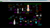
Synthesis Gas Section Overview
Synthesis gas is produced by steam reforming of methane contained in natural gas. Steam reforming is extensively used in the commercial production of ammonia, hydrogen and methanol. Steam and methane react over a nickel-based catalyst to form a mixture of carbon monoxide, hydrogen, unreacted methane and unreacted steam:
Heat + CH4 + H2O = CO + 3H2
The steam reforming reaction takes place in the vapor phase and is endothermic so heat is added externally. Heat is also added co-currently in the process by injecting oxygen to burn a portion of the methane prior to passing the feed mixture over a fixed bed of steam reforming catalyst. For production of hydrocarbons via the Fischer-Tropsch reaction, the operating conditions and ratios of steam and oxygen to natural gas feed will produce synthesis gas with a hydrogen-to-carbon monoxide molar ratio of roughly 2.0.
Carbon dioxide (CO2) is also produced in the reformers due to the water-gas shift reaction:
CO + H2O = CO2 + H2 + heat
Although this reaction produces more hydrogen, it also consumes carbon monoxide, making it undesirable. Higher concentrations of CO2 are thermodynamically favored at lower reaction temperatures. Because the GTL reformer conditions are at high temperature, CO2 formation is minimized.
Feed natural gas from battery limits is preheated in E-101 using warm flue gas from the Steam Reforming Furnace F-101. Hydrogen is added to the warm feed prior to entering Hydrodesulfurizer R-101A. This reactor converts sulfur compounds such as mercaptans and thiophenes to hydrogen sulfide (H2S) which easily reacts with solid zinc oxide in R-101B. Removal of sulfur compounds from the feed gas safeguards the activity of the catalysts used in the GTL process.
Low-sulfur natural gas from R-101B is further heated by flue gas in E-102 and combines with superheated high pressure steam from E-103 prior to being fed to the top of the Pre-reformer Reactor R-102. R-102 converts all the ethane and heavier hydrocarbons in the feed gas to CH4, CO and CO2 via the steam reforming reaction. Because R-102 is well-insulated, the temperature of the process gas mixture decreases from the reforming reaction.
The outlet gas from R-102 passes on to Feed Heater F-101. F-101 is a fired process heater and provides the heat to bring the following streams up to the desired operating temperatures (refer to Schematic #4 in the “Process Schematics” section below):
- Feed gas to Desulfurizer R-101A (via E-101)
- Feed gas/steam mixture to Pre-reformer R-102 (via E-102)
- High pressure steam produced by the Waste Heat boiler E-104 (via E-103)
- Partially reformed feed gas/steam mixture to Autothermal Reformer R-103 (via the radiant section of F-101)
F-101 is a natural draft heater that uses natural gas for fuel.
Partially reformed feedgas from F-101 is sent to the Autothermal Steam Reformer R-103. Oxygen and superheated high pressure steam from E-103 are injected into the reformed gas feed in a specially designed burner in the top of R-103. The very hot burner outlet gas passes down over nickel-based catalyst in R-103. As the steam reforming reaction progresses over the catalyst, the temperature drops as heat is absorbed from the reactants.
The hot outlet gas from R-103 is cooled in Waste Heat Boiler E-104 which generates high pressure steam in Steam Drum D-101. Steam from D-101 is superheated in E-103 using hot flue gas from the radiant section of F-101. Any superheated steam not used in the GTL plant is sent to the high pressure steam system at battery limits.
The synthesis gas is further cooled in Boiler Feed Water Preheater E-105. The synthesis gas is cooled by cooling water in Synthesis Gas Cooler E-106 to condense as much excess process steam as possible. Process condensate is separated in Process Condensate Separator D-102. Synthesis gas from D-102 is taken off to the GTL reactor section. Process condensate is sent to battery limits for treatment prior to reuse as boiler feedwater.
The Recycle Compressor K-101 is normally only used at startup to circulate nitrogen for warming the process up prior to introduction of steam and then feed gas.
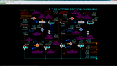
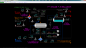
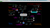
F-T Reactor Section Overview
The Fischer-Tropsch reaction refers to the collection of reactions that convert carbon monoxide and hydrogen to hydrocarbons and water. To produce an alkane (saturated hydrocarbon) the reaction equation is generalized as:
CO + 2H2 = -CH2- + H2O + heat
Where -CH2- is the interior segment of an alkane molecule. The reaction produces a mixture of hydrocarbons of varying carbon lengths. In the GTL simulator, the highest molecular weight compound produced is eicosane (C20H44). The reaction occurs in the vapor phase and is highly exothermic. Heat is removed to keep the reactor temperature from becoming too high which results in sub-optimal hydrocarbon yield and, potentially, equipment damage.
The conversion of reactants by the Fischer-Tropsch reaction is constrained by chemical equilibrium. To increase conversion two reactor systems are provided. The products from the first Fischer-Tropsch reactor are condensed and removed. The remaining unreacted synthesis gas is sent to a second reactor system.
Synthesis gas from the Process Condensate Separator D-102 is preheated to the reaction initiation temperature using high pressure steam in 1st Stage Preheater E-201 and enters 1st Stage F-T Reactor R-201. R-201 consists of modular catalyst layers that are engineered to promote very high reaction rates in a relatively small volume. Heat of reaction is removed by generating steam in the reactor itself. The modular catalyst layers transfer heat through embedded cooling channels to circulating boiler water from 1st Stage Steam Drum D-201 and 1st Stage Water Pumps P-201A/B. The pressure of D-201 is varied to control the reactor temperature. Steam from D-201 is let down to the medium pressure steam system at battery limits.
Condensation and removal of products is done at two different temperatures to make a rough separation of the hydrocarbons. The heavier, waxy hydrocarbons and some of the water produced in R-201 will be condensed in 1st Stage Boiler Feed Water Preheater E-202. The waxy hydrocarbon and the condensed water are separated in 1st Stage Hot Separator D-202 and sent off to battery limits for treatment and separation. The vapor from D-202 will be further cooled in 1st Stage Reactor Product Cooler E-203. A lighter hydrocarbon mixture and more water are condensed in E-203. These are separated in 1st Stage Cold Separator D-203 and taken off to battery limits.
The synthesis gas from D-203 is sent to the 2nd Stage F-T Reactor system which is nearly identical in layout to the 1st Stage F-T Reactor system. The pressure in the entire process is controlled by adjusting the flow of tailgas from the 2nd Stage Cold Separator D-303 to a hydrogen recovery unit at battery limits. Condensed hydrocarbons and water are taken off to battery limits for treatment and separation.
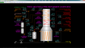
Feed Preheat Section
Feed Gas Preheat Section No. 1
High pressure (HP) natural gas from battery limits is preheated in Feed Gas Preheater No. 1 E-101, in the stack of Feed Heater F-101. HP nitrogen (N2) is added to the line at startup and when the feed gas is tripped out. Nitrogen keeps the reforming catalysts in the process from reacting with unwanted compounds such as oxygen which oxidizes the metal on the catalysts. Nitrogen also sweeps out natural gas after a feed gas trip to prevent carburization (coking) of the reforming catalysts under low steam conditions.
Recycle gas from K-101 is also added to the feed gas line. The recycle compressor is used at startup to circulate nitrogen throughout the front end while warming up the reactors.
A bypass line around E-101 is used to keep the temperature of warm feed gas going to R-101A from becoming too high in case of transient conditions. Normally no feed gas bypasses E-101. Warm flue gas from E-102 is used to warm the feed gas in E-101.
The stack damper for Feed Heater F-101 is located above E-101 and is adjusted to provide the desired amount of draft in the radiant box of F-101.
R-101A/B Desulfurizer
Warm feedgas from E-101 is combined with makeup hydrogen (H2) from battery limits and fed to Desulfurizer R-101A which contains a catalyst bed made of cobalt and molybdenum as the active metals which will convert more complex sulfur-containing compounds in the feedgas to hydrogen sulfide (H2S). These compounds are typically low in concentration in natural gas, but they are high enough that they would poison the reforming and F-T catalysts in the process over time. Hydrogen is added to convert these compounds because it is a reactant; the reaction is known as hydrodesulfurization. For example, thiophene (C4H4S) is a common sulfur-containing compound and reacts with hydrogen as follows:
C4H4S + 4H2 = C4H10 (butane) + H2S + heat
A relatively high concentration of hydrogen compared to the concentration of the sulfur species in the feed gas makes the conversion to H2S nearly 100% at the typical operating temperature of R-101A. Normally, there is no temperature rise across R-101A from the desulfurization reactions because of the very low concentrations of the sulfur species. There is normally a small temperature decrease owing to heat loss from the walls of the reactor. However, if olefins - e.g. ethylene (C2H4) and propylene (C3H6) - are present in significant concentrations in the feed, the hydrogenation of these compounds will result in a large release of reaction heat:
C2H4 + H2 = C2H6 (ethane) + heat
Olefins are not normally present in natural gas, but can be present if a process gas containing olefins from a chemical plant is mixed in with the feed. If the concentration of olefins is high enough, it will cause the outlet temperature of R-101A to rise to unacceptable levels. Olefins easily hydrogenate in R-101A. Olefins are undesirable because they are more susceptible to coking on the steam reforming catalysts, even in the presence of sufficient process steam.
R-101B contains a catalyst bed of zinc oxide (ZnO) which will react with the H2S produced by R-101A to form zinc sulfide (ZnS) and water (H2O):
ZnO + H2S = ZnS + H2O + heat
Zinc sulfide remains as a solid in the catalyst bed and accumulates over time, starting from the top of the bed and moving downward. The catalyst bed of R-101B is sized to absorb H2S over a period of two years without needing to be replaced. The H2S concentration in the feed gas to R-101B is very low so that the heat of reaction does not increase the temperature across R-101B.
Feed Gas Preheat Section No. 2
Desulfurized feed gas from R-101B is further heated in Feed Gas Preheater No. 2 E-102 using warm flue gas from HP Steam Superheater E-103. Maximum heat recovery is desired in E-102 to maintain the highest possible feed gas temperature to Pre-reformer R-102, so there is no feed gas bypass line around E-102.
E-103 heats saturated HP steam generated in Steam Drum D-101 using hot flue gas from the radiant section of Feed Heater F-101. A bypass line around E-103 is provided in case the superheat becomes excessive during transient conditions. Normally, no steam bypasses E-103.
The main HP steam distribution header for the plant is located at the outlet of E-103. Superheated steam is supplied to:
- Pre-reformer R-102 (main process steam)
- Autothermal Reformer R-103 (seal steam)
- 1st Stage F-T Reactor Feed Preheater E-201 (process heating)
- 2nd Stage F-T Reactor Feed Preheater E-301 (process heating)
Excess steam is exported to the site’s HP steam system at battery limits. An atmospheric vent is provided for use at startup and shutdown.
At startup, the GTL plant cannot produce sufficient HP steam to satisfy process requirements to permit natural gas to be admitted. Therefore, a startup line is provided at the outlet of Steam Drum D-101 (see Schematic #9) to import HP steam from the site steam system at battery limits until the GTL plant produces its own steam at normal rates in D-101.
F-101 Radiant Section and Pre-reformer R-102
HP superheated steam from E-103 is combined with warm, desulfurized feed gas from E-102 and fed to Pre-reformer R-102. The catalyst bed in R-102 contains nickel as the active metal for the reforming reaction between steam and hydrocarbon compounds (mainly methane and smaller concentrations of ethane and propane). The main purpose of R-102 is to break down the ethane and heavier hydrocarbons into CO and H2 via the steam reforming reaction. These heavier hydrocarbons would tend to promote coking in the Autothermal Reformer, R-103. The secondary purpose of R-102 is to partial convert some of the feed methane to CO and H2. Although the reforming reaction absorbs heat, a significant conversion of the CO to CO2 via the water-gas shift reaction occurs in R-102 owing to its relatively low temperature. The net effect is the temperature across the reactor rises modestly.
The partially reformed synthesis gas from R-102 is further heated in the radiant section of Feed heater F-101. As mentioned earlier, F-101’s main purpose is to provide enough heating of the feed gas to attain the desired temperatures in R-101A and R-102. The outlet temperature of the gas from F-101 is not particularly critical to the performance in the Autothermal Reformer R-103. Rather, the temperature has to be such that it produces enough hot flue gas to satisfy the feed gas preheating and steam superheating requirements in E-101, E-102 and E-103.
F-101 is a conventional natural draft process heater. Low pressure natural gas is used for the fuel. The radiant box pressure is kept slightly less than atmospheric to draw ambient air in through the air damper which supplies the burners. The stack damper for regulating draft is located at the top of the stack (see Schematic #5). F-101 assumes pilot burners are always lit so that combustion of fuel gas occurs whenever it is introduced into the radiant box.
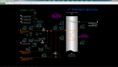
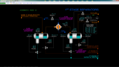
Autothermal Reformer and Waste Heat Boiler
Autothermal Reformer R-103
The Autothermal Reformer R-103 is essentially a combination burner and steam reformer catalyst bed. Nearly pure oxygen is mixed and burned with partially reformed synthesis gas from Feed Heater F-101 in a specially designed burner outfitted in the top section of R-103. A small flow of steam is added to the oxygen line to serve as a seal fluid to prevent hot gases from reversing into the oxygen feed line if the oxygen flow is stopped.
The amount of oxygen added to R-103 is much less than the theoretical amount to fully combust the carbon of the methane in synthesis gas. This partial oxidation environment favors the production of synthesis gas rich in CO. The partial combustion of the feed carbon in the burner also releases a large amount of heat which is absorbed as the unburned methane is converted to CO and H2 over the catalyst bed of R-103 via the reforming reaction. As a consequence, the temperature of the synthesis gas decreases along the depth of the catalyst bed. Despite this heat absorption, the outlet temperature from R-103 is still quite high (around 1,881 DEG F which favors a lower concentration of CO2 in the exiting synthesis gas via the water-gas shift reaction.
Waste Heat Boiler E-104
Hot synthesis gas from R-103 enters immediately into Waste Heat Boiler E-104 to generate HP steam from circulating water from the HP Steam Drum D-101. E-104 and its connection to R-103 are specially design to handle the large thermal stresses resulting from the high differential temperature between the synthesis gas and the circulating boiler water.
HP Steam Drum D-101
D-101 receives preheated boiler feedwater from Boiler Feedwater Preheater E-105. D-101 supplies E-104 with water through a series of downcomers. As the water absorbs heat from the synthesis gas, it partially boils the circulating water causing it to lift through the risers back to D-101 (natural circulation). A specially designed separator within D-101 separates the steam and routes it to the outlet steam line from D-101. The separated return water is cycled back to the downcomers. A blowdown line is provided to continuously purge water from D-101. Purging prevents the buildup of non-volatile compounds in the boiler feed water which would foul E-104 if their concentrations became too high.
Saturated HP steam from D-101 is routed to E-103 to be superheated before being used as process, heating and export steam. An atmospheric vent of the saturated steam header is provided for use at startup and shutdown. HP steam from the site steam system is provided from battery limits to supply process and heating steam at startup before feed gas and oxygen is admitted into the front end of the GTL plant.
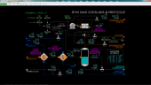
Synthesis Gas Cooling Section Process
Boiler Feedwater Preheater E-105
Very warm synthesis gas from Waste Heat Boiler E-104 is further cooled in Boiler Feedwater Preheater E-105 using HP boiler feedwater from battery limits. The flow rate of boiler feedwater is dependent on the steam generation in HP Steam Drum D-101.
Synthesis Gas Cooler E-106
Final cooling of the synthesis gas is done in Synthesis Gas Cooler E-106 using cooling water from battery limits. A large amount of excess process steam added to Pre-reformer R-102 is also condensed as the synthesis gas cools.
Process Condensate Separator D-102
Synthesis gas and process condensate from E-106 are separated in Process Condensate Separator D-102. The process condensate is taken off to battery limits for treatment prior to reuse as makeup boiler feedwater at the site.
Synthesis gas vapor from D-102 contains mostly H2 and CO in a molar ratio of 2.26. Residual concentrations of CH4, CO2, N2 and water vapor make up the rest of the synthesis gas. Synthesis gas is normally routed to 1st Stage Feed Preheater E-201 prior to being fed to the 1st Stage F-T Reactor R-201. The pressure of the synthesis gas in D-102 is sufficiently high to promote the F-T reaction at a high rate so that no compression of the synthesis gas is required to make liquid products. Synthesis gas from D-102 can be routed to the flare system at battery limits in case of a trip of the back end of the GTL Plant and during normal shutdown and startup.
Recycle Compressor K-101
Gas from D-102 can also be recirculated back to the feed gas line upstream of Feed Preheater No. 1 E-101. This is normally done during startup when the unit is filled with nitrogen in order to heat up the reactors in the front end. Recycle Compressor K-101 is an electric motor driven reciprocating compressor. K-101 is outfitted with a continuous volume control system so that the recycle flow rate can be adjusted if necessary. As K-101 is a volumetric machine, it will deliver more total mass flow the higher its suction pressure. K-101 is also outfitted with suction and discharge isolation valves.
1st Stage F-T Reactor Section
1st Stage Feed Preheater E-201
Cool synthesis gas from D-102 is heated close to the temperature of 1st Stage F-T Reactor R-201. This is done so that the maximum reaction rate is attained throughout all of the volume of R-102. 1st Stage Feed Preheater E-201 uses superheated HP steam from E-103 as the heating medium. Condensed steam from E-201 collects on the shell side of E-201 and is routed to the HP Condensate collection header at battery limits. Nitrogen is added upstream of E-201 during startup to warm up R-201 prior to the introduction of synthesis gas. It is also added if R-201 is tripped to sweep out synthesis gas from the reactor.
1st Stage F-T Reactor R-201
1st Stage F-T Reactor R-201 consists of modular catalyst layers that transfer heat from the reaction of synthesis gas from E-201 through embedded cooling channels to circulating boiler water from 1st Stage Water Pumps P-201A/B. The partially boiled water from R-201 is returned to 1st Stage Steam Drum D-201.
1st Stage Water Pumps P-201A/B
1st Stage Water Pumps P-201A/B are motor driven centrifugal pumps that circulate boiler water from 1st Stage Steam Drum D-201 through R-201. The water circulation flow rate is very high relative to the net steam rate generated in D-201. Only one of the pumps is normally in service. An auto-start circuit is provided to start the standby pump if the circulating water flow rate is too low.
1st Stage Steam Drum D-201
D-201 receives preheated boiler feedwater from 1st Stage Boiler Feedwater Preheater E-202. D-201 supplies P-201A/B with water for cooling R-201. A specially designed separator within D-201 separates the steam from the return stream from R-201 and routes it to the outlet steam line from D-201. The separated return water is cycled back to the base of D-201. Saturated MP steam from D-201 is routed to battery limits for use at the site. An atmospheric vent is provided to depressure D-201 in case of a trip of R-201. A lower pressure in D-201 helps cool R-201 faster because the circulating water boils at a lower temperature.
1st Stage Boiler Feedwater Preheater E-202
Warm synthesis gas and F-T hydrocarbon product from R-201 is cooled in 1st Stage Boiler Feedwater Preheater E-202 using MP boiler feedwater from battery limits. The flow rate of boiler feedwater is dependent on the steam generation in 1st Stage Steam Drum D-201. The heavier hydrocarbon compounds formed in R-201 are condensed in E-202 as is some of the water produced by the F-T reaction.
1st Stage Hot Separator D-202
1st Stage Hot Separator D-202 is a three-phase separator which separates the heavier hydrocarbons and water condensed in E-202 from the unreacted synthesis gas leaving R-201. The effluent from E-202 enters over the water side of the separator. The hydrocarbon phase will float and accumulate on top of the water phase and spill over a baffle into the hydrocarbon side of the separator so that each liquid can be withdrawn independently. The vapor exits at the top of the separator. A mesh screen coalesces any liquid droplets entrained in the vapor and returns it to the liquid holdup by gravity. The separated liquids are taken off to battery limits for further processing.
1st Stage Reactor Product Cooler E-203
The vapor from D-202 is further cooled as much as possible in 1st Stage Reactor Product Cooler E-203 using cooling water from battery limits. Lighter hydrocarbons and more water are condensed in E-203 owing to its lower outlet temperature than E-202.
1st Stage Cold Separator D-203
1st Stage Cold Separator D-203 is a three-phase separator which separates the heavier hydrocarbons and water condensed in E-203 from the unreacted synthesis gas leaving R-201. It functions exactly like D-202. The separated liquids are taken off to battery limits for further processing.
Vapor from D-203 still contains mostly CO and H2 and is normally sent to 2nd Stage Feed Preheater E-301. Because of reaction in R-201 and removal of water and hydrocarbons in D-202 and D-203, the concentrations of CH2, CO2 and N2 are higher than in the synthesis gas fed to the R-201. Vapor from D-203 can also be sent to flare during startup, shutdown and emergencies such as a trip of the 2nd Stage F-T Reactor R-301.
2nd Stage F-T Reactor Section
The 2nd Stage F-T Reactor Section is essentially identical in function to the 1st Stage F-T Reactor Section. However, it handles approximately 25% of the feed rate to the 1st Stage. The tail gas from the last separator is normally sent to a hydrogen recovery unit at battery limits because it is rich in hydrogen.
2nd Stage Feed Preheater E-301
Cool synthesis gas from D-203 is heated close to the temperature of 2nd Stage F-T Reactor R-301. 2nd Stage Feed Preheater E-301 uses superheated HP steam from E-103 as the heating medium. Condensed steam from E-301 collects on the shell side of E-301 and is routed to the HP Condensate collection header at battery limits. Nitrogen is added upstream of E-301 during startup to warm up R-301 prior to the introduction of synthesis gas. It is also added if R-301 is tripped to sweep out synthesis gas from the reactor.
2nd Stage F-T Reactor R-301
2nd Stage F-T Reactor R-301 consists of modular catalyst layers that transfer heat from the reaction of synthesis gas from E-301 through embedded cooling channels to circulating boiler water from 2nd Stage Water Pumps P-301A/B. The partially boiled water from R-301 is returned to 2nd Stage Steam Drum D-301.
2nd Stage Water Pumps P-301A/B
2nd Stage Water Pumps P-301A/B are motor driven centrifugal pumps that circulate boiler water from 2nd Stage Steam Drum D-301 through R-301. The water circulation flow rate is very high relative to the net steam rate generated in D-301. Only one of the pumps is normally in service. An auto-start circuit is provided to start the standby pump if the circulating water flow rate is too low.
2nd Stage Steam Drum D-301
D-301 receives preheated boiler feedwater from 2nd Stage Boiler Feedwater Preheater E-302. D-301 supplies P-301A/B with water for cooling R-301. A specially designed separator within D-301 separates the steam from the return stream from R-301 and routes it to the outlet steam line from D-301. The separated return water is cycled back to the base of D-301. Saturated MP steam from D-301 is routed to battery limits for use at the site. An atmospheric vent is provided to depressure D-301 in case of a trip of R-301. A lower pressure in D-301 helps cool R-301 faster because the circulating water boils at a lower temperature.
2nd Stage Boiler Feedwater Preheater E-302
Warm synthesis gas and F-T hydrocarbon product from R-301 is cooled in 2nd Stage Boiler Feedwater Preheater E-302 using MP boiler feedwater from battery limits. The flow rate of boiler feedwater is dependent on the steam generation in 2nd Stage Steam Drum D-301. The heavier hydrocarbon compounds formed in R-301 are condensed in E-302 as is some of the water produced by the F-T reaction.
2nd Stage Hot Separator D-302
2nd Stage Hot Separator D-302 is a three-phase separator which separates the heavier hydrocarbons and water condensed in E-302 from the unreacted synthesis gas leaving R-301. The vapor exits at the top of the separator. A mesh screen coalesces any liquid droplets entrained in the vapor and returns it to the liquid holdup by gravity. The separated liquids are taken off to battery limits for further processing.
2nd Stage Reactor Product Cooler E-303
The vapor from D-302 is further cooled as much as possible in 2nd Stage Reactor Product Cooler E-303 using cooling water from battery limits. Lighter hydrocarbons and more water are condensed in E-303 owing to its lower outlet temperature than E-302.
2nd Stage Cold Separator D-303
2nd Stage Cold Separator D-303 is a three-phase separator which separates the heavier hydrocarbons and water condensed in E-303 from the unreacted synthesis gas leaving R-301. It functions exactly like D-302. The separated liquids are taken off to battery limits for further processing.
Vapor from D-303 is rich in H2 and CH4 and is normally sent off as tail gas to a hydrogen recovery unit at battery limits.
Vapor from D-303 can also be sent to flare during startup, shutdown and emergencies such as a trip of the 2nd Stage F-T Reactor R-301.
Instrumentation
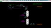
1st Preheat Section
HP natural gas feed gas from battery limits is controlled by FIC-101 by adjusting the position of control valve FV-101. The pressure and temperature of the HP natural gas supply are indicated on PI-412 and TI-412 respectively. The PV of FIC-101 is connected to the setpoint of controllers FIC-103 (hydrogen to R-101A), FIC-102 (steam to R-102) and FIC-121 (oxygen to R-103) so their setpoints can be automatically adjusted in ratio to changes in the feed gas flow. In the event of a feed gas trip (see Feed Trip Interlock I-101 below), FIC-101 is locked in manual mode with an output of 0%.
HP nitrogen from battery limits is controlled by HIC-101 by adjusting the position of control valve HV-109. The flow of HP nitrogen is indicated on FI-109. The pressure and temperature of the HP nitrogen supply are indicated on PI-451 and TI-451 respectively. In the event of a feed gas trip (see Feed Trip Interlock I-101 below), HIC-109 is opened in manual mode with an output of 100% in order to sweep nitrogen into the front end to protect the catalysts in the reactors from coking and oxidation. This adjustment is done only once per trip so that manual control of HIC-109 can be made thereafter as needed. FI-109 is used by Feed Heater interlock I-102 (see interlock I-102 below) to compute the total flow through F-101’s radiant tubes.
The flow of gas from Recycle Compressor K-101 is indicated on FI-139. The temperature of the recycle gas is indicated on TI-139. FI-139 is used by Feed Heater interlock I-102 to compute the total flow through F-101’s radiant tubes.
The pressure and temperature of the feed gas line upstream of Feed Gas Preheater E-101 are indicated on PI-101 and TI-101 respectively. The outlet temperature of feed gas from E-101 is indicated on TI-102. The combined feed gas stream to Desulfurizer R-101A is indicated on TIC-103 which controls the position of E-101 bypass valve TV-103. The setpoint of TIC-103 is set to avoid a high temperature of gas to R-101A so there is normally no flow through TV-103. The flue gas temperature to E-101 is indicated on TI-114. The outlet flue gas temperature from E-101 is indicated on TI-115.
The oxygen content of flue gas in the stack of Feed Heater F-101 is indicated on AI-115. The opening of stack damper PV-111 is controlled by radiant box draft controller PIC-111.
Desulfurizer
Hydrogen from battery limits is controlled by FIC-103 by adjusting the position of control valve FV-103. The pressure and temperature of the hydrogen supply are indicated on PI-421 and TI-421 respectively. The PV of feed gas flow controller FIC-101 is connected to the setpoint of FIC-103. FIC-103 is normally in cascade mode so that its setpoint will automatically adjust in a ratio to the feed gas flow. When FIC-103 is in automatic or manual mode, the ratio parameter of FIC-103 will automatically be set so that there is no bump of the setpoint of FIC-103 when it is placed into cascade mode (auto-ratio control). To change the ratio parameter of FIC-103 to a new value, place FIC-103 from cascade into automatic mode, make the new hydrogen setpoint change, allow the hydrogen flow to stabilize and then place FIC-103 back into cascade mode.
Whenever the Feed Trip Interlock I-101 is active, FIC-103 will be locked in manual mode with an output of 0%.
The inlet pressure and temperature of feedgas to Desulfurizer R-101A are indicated on PI-104 and TI-104, respectively. The mid-bed temperature of R-101A is indicated on TI-105. The outlet temperature from R-101A is indicated on TI-106. The outlet pressure and temperature from Zinc Oxide (ZnO) Sulfur Absorber R-101B are indicated on PI-107 and TI-107 respectively.
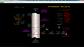
2nd Preheat Section
The outlet pressure and temperature from Zinc Oxide (ZnO) Sulfur Absorber R-101B are indicated on PI-107 and TI-107 respectively. The feed gas outlet pressure and temperature from Feed Gas Preheater No. 2 E-102 are indicated on PI-108 and TI-108 respectively. The flue gas outlet temperature from E-102 is indicated on TI-114.
The temperature of saturated steam to HP Steam Superheater E-103 is indicated on TI-120. The outlet temperature of superheated steam from E-103 is indicated on TI-109. The temperature of flue gas temperature to E-103 is indicated on TI-112; the outlet temperature is indicated on TI-113.
The superheated HP steam header temperature is controlled by TIC-110 which adjusts the opening of E-103 bypass control valve TV-110. The pressure of the header is controlled by PIC-124 which adjusts the opening of excess HP steam control valve PV-124. The flow of exported steam is indicated on FI-124.
F-101 Radiant Section and Pre-reformer
The feed gas outlet pressure and temperature from Feed Gas Preheater No. 2 E-102 are indicated on PI-108 and TI-108 respectively.
Pre-reformer R-102
HP superheated steam from E-103 to Pre-reformer R-102 is controlled by FIC-102 by adjusting the position of control valve FV-102. The PV of feed gas flow controller FIC-101 is connected to the setpoint of FIC-102. FIC-102 is normally in cascade mode so that its setpoint will automatically adjust in a ratio to the feed gas flow. When FIC-102 is in automatic or manual mode, the ratio parameter of FIC-102 will automatically be set so that there is no bump of the setpoint of FIC-102 when it is placed into cascade mode (auto-ratio control). To change the ratio parameter of FIC-102 to a new value, place FIC-102 from cascade into automatic mode, make the new process steam setpoint change, allow the steam flow to stabilize and then place FIC-102 back into cascade mode.
FAL-102 independently measures the steam flow to R-102 and is used as the main trip sensor for Feed Trip Interlock I-101 which protects the reforming catalysts in R-102 and Autothermal Reformer R-103 from coking under low steam flow conditions. See Feed Trip Interlock I-101 below for details of the trip logic. FAL-102 is also used by Feed Heater Interlock I-102 to calculate the mass flow through the tubes of F-101. ES-101 is a trip switch to manually activate and to reset I-101. XA-101 is an alarm that indicates when I-101 has tripped. When I-101 activates, steam flow controller FIC-102 is taken out of cascade mode so that steam flow will remain nearly steady as feed gas flow FIC-101 stops.
The inlet temperature of feedgas and steam to R-102 is indicated on TI-116A. TI-116B indicates the catalyst bed temperature at 33% depth in R-102 and TI-116C indicates the temperature at 66% depth. The outlet temperature from R-102 is indicated on TI-116D.
F-101 Radiant Section
The outlet temperature of partially reformed feed gas from F-101 is controlled by TIC-117 which adjusts the setpoint of fuel gas flow controller FIC-112. TAH-117 independently measures the outlet temperature and is used as a trip sensor for F-101 Firing Interlock I-102 (see interlock details below). I-102 also computes the calculated mass flow through F-101 and is indicated on FAL-117 and is expressed as % of design flow. FAL-117 serves as a virtual trip sensor for I-102. ES-102 is a trip switch to manually activate and to reset I-102. XA-102 is an alarm that indicates when I-102 has tripped.
The fuel gas flow to the radiant box of Feed Heater F-101 is controlled by FIC-112 which adjusts the opening of fuel gas control valve FV-112. The fuel gas supply pressure and temperature are indicate on PI-411 and TI-411 respectively. The specific gravity of fuel gas is indicated on AI-411.
The opening of the combustion air damper HV-111 is controlled by HIC-111. The temperature of ambient air is indicated on TI-111. If F-101 Firing Interlock I-102 is activated, HIC-111 will be fully opened on a one-shot basis. This will maximize combustion air flow to help cool F-101. The oxygen content of the stack flue gas is indicated on AI-115 (see schematic #5). Adjusting the opening of HIC-111 controls the oxygen content.
The draft pressure of the radiant box of F-101 is controlled by PIC-111 which adjusts the opening of the stack damper PV-111 on the cold end of the stack of F-101. The pressure of the box is kept slightly below atmospheric to draw air in through the combustion air damper. The stack effect (hot air rises and hotter air rises faster) draws flue gas from the radiant box up the stack. Stack damper PV-111 allows adjustment of the flue gas flow rate through the stack such that a slightly negative pressure is maintained in the box. PAH-111 is an independent measurement of the box pressure that is used by I-102. If this pressure becomes too high, I-102 will activate. When I-102 activates, the stack damper controller PIC-111 will be fully opened on a one-shot basis to maximize air flow into the radiant box. The flue gas temperature leaving the radiant box is indicated on TI-112.
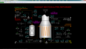
Autothermal Reformer and Waste Heat Boiler
Autothermal Reformer R-103
The pressure of partially reformed feed gas entering Autothermal Reformer R-103 is indicated on PI-121. The oxygen flow from battery limits is controlled by FIC-121 by adjusting the position of control valve FV-121. The pressure and temperature of the oxygen supply are indicated on PI-422 and TI-422 respectively. The PV of feed gas flow controller FIC-101 is connected to the setpoint of FIC-121. FIC-121 is normally in cascade mode so that its setpoint will automatically adjust in a ratio to the feed gas flow. When FIC-121 is in automatic or manual mode, the ratio parameter of FIC-121 will automatically be set so that there is no bump of the setpoint of FIC-121 when it is placed into cascade mode (auto-ratio control). To change the ratio parameter of FIC-121 to a new value, place FIC-121 from cascade into automatic mode, make the new hydrogen setpoint change, allow the hydrogen flow to stabilize and then place FIC-121 back into cascade mode.
Whenever the Feed Trip Interlock I-101 is active, FIC-121 will be locked in manual mode with an output of 0%.
Seal steam flow to the burner of R-103 is controlled by FIC-122 which adjusts the opening of control valve FV-122. The seal steam flow is very small compared to the process steam flow FIC-102 to Pre-reformer R-102.
The temperature at the top section of catalyst bed in R-103 is indicated on TI-121A. The mid-bed temperature is indicated on TI-121B and the lower bed temperature is indicated on TI-121C. The outlet temperature of R-103 is indicated on TI-122. The outlet pressure is indicated on PI-122.
Waste Heat Boiler E-104 and HP Steam Drum D-101
The outlet temperature of synthesis gas from Waste Heat Boiler E-104 is indicated on TI-124.
The level of water in HP Steam Drum D-101 is controlled by LIC-123 which adjusts the setpoint of boiler feedwater flow controller FIC-123 (see Schematic #10). LAL-123 is an independent measurement of the water level and is used by both Feed Trip Interlock I-101 and F-101 Firing Interlock I-102 as a trip sensor to prevent excessive temperatures from reaching past E-104. Blowdown flow from D-101 is controlled using HIC-125 which adjusts the opening of control valve HV-125. The flow of blowdown water is indicated on FI-125. The pressure of D-101 is indicated on PI-123.
HIC-123 opens control valve HV-123 to vent D-101 to atmosphere as needed during startup, shutdown and emergencies.
FIC-126 controls the flow of HP steam from the site steam system for startup by adjusting the position of control valve FV-126. The supply pressure of HP steam is indicated on PI-401.
Synthesis Gas Cooling and Recycle Compressor
Boiler Feedwater Preheater E-105
The synthesis gas outlet temperature from Boiler Feedwater Preheater E-105 is indicated on TI-125. The flow of HP boiler feedwater from battery limits to E-105 is controlled by FIC-123 which adjusts the position of control valve FV-123. The pressure and temperature of the HP boiler feedwater supply is indicated on PI-402 and TI-402 respectively. The boiler feedwater outlet temperature from E-105 is indicated on TI-123.
Synthesis Gas Cooler E-106
The synthesis gas outlet temperature from Synthesis Gas Cooler E-106 is indicated on TI-126. The flow of cooling water from battery limits to E-106 is controlled by HIC-126 which adjusts the position of control valve HV-126. The pressure and temperature of the cooling water supply is indicated on PI-403 and TI-403 respectively.
Process Condensate Separator D-102
The level of condensate collected in Process Condensate Separator D-102 is controlled by LIC-131 which adjusts the position of control valve LV-131. The flow rate of process condensate from D-102 to battery limits is indicated on FI-131. LAH-131 is an independent level instrument that serves as a trip sensor for Recycle Compressor Interlock I-103. High level will trip Recycle Compressor K-101.
The pressure of D-102 is controlled by PIC-131 which adjusts the flare release control valve PV-131 in case the pressure of D-102 becomes too high. Normally PV-131 is closed. An alarm will sound (ZI-131) if the output of PIC-131 is not 0% to indicate a release to flare. The flow of synthesis gas from D-102 to 1st Stage Feed Preheater E-201 is controlled by HIC-132 which adjusts the position of control valve HV-132. The flow rate of synthesis gas through HV-132 is indicated on FI-132. HIC-132 is locked in manual with an output of 0% in case of a trip of the 1st Stage F-T Reactor.
Composition analysis of the synthesis gas to E-201 is indicated by AI-132A~E. The volume % of CH4, CO, H2, CO2 and N2 are provided.
Recycle Compressor K-101
The motor of Recycle Compressor K-101 is turned on and off by hand switch HS-133. The compressor suction and discharge isolation valves XV-134A/B are opened and closed by common hand switch HS-134. HS-134 must be in the OPEN position for K-101’s motor to operate (see I-301 below). HIC-133 adjusts the volumetric capacity of K-101 continuously from 0 to 100%. TI-139 indicates the discharge temperature of K-101 and FI-139 indicates the flow of recycle gas to Feed Preheater No. 1 E-101.
K-101 is protected by Recycle Compressor interlock I-103. ES-103 is a hand switch to manually activate the interlock. XA-103 is an alarm that signals that I-103 has been activated. XI-133 is an alarm that indicates mechanical trouble with K-101. XA-133 is an alarm that the compressor has tripped due to a potentially damaging mechanical problem. See the section on I-103 below for details of the interlock logic.
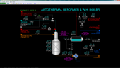
1st Stage F-T Reactor Section
1st Stage Feed Preheater E-201
HP nitrogen flow from battery limits to 1st Stage Feed Preheater E-201 is controlled by HIC-207 which adjusts the position of control valve HV-207.
The flow rate of nitrogen is indicated on FI-207. The flow of HP steam to E-201 is stopped by closing hand switch HS-201. HS-201 will close isolation valve XV-201. HS-201 is locked in the closed position whenever the 1st Stage F-T Reactor Interlock I-201 is active. The flow rate of steam is indicated on FI-201. TIC-201 controls the synthesis gas temperature leaving E-201 by regulating the position of high pressure condensate control valve TV-201. The regulation of TV-201 results in a change of the condensate level on the shell side of E-201 which, in turn, exposes more or less tube area for heat transfer by condensing HP steam. TIC-201 is locked in manual with 0% output when I-201 is active.
ES-201 is a hand switch to manually activate interlock I-201. XA-201 is an alarm that signals that I-201 has been activated.
The outlet pressure of synthesis gas leaving E-201 is indicated on PI-201.
1st Stage F-T Reactor R-201
The outlet temperature of 1st Stage F-T Reactor R-201 is indicated on TI-203. TAH-203 is an independent trip sensor for 1st Stage F-T Reactor Interlock I-201.
1st Stage Water Pumps P-201A/B
The motor for 1st Stage Water Pump P-201A is operated by hand switch HS-201A. The pump may be placed in auto-start mode by placing hand switch HS-202A in the AUTO position. The motor for 1st Stage Water Pump P-201B is operated by hand switch HS-201B. The pump may be placed in auto-start mode by placing hand switch HS-202B in the AUTO position.
FAL-203 indicates the flow rate of circulating water from 1st Stage Steam Drum D-201 to R-201. A low flow on FAL-203 will be used as the auto-start signal if HS-202A or HS-202B is in the AUTO state. If FAL-203 remains low for an extended time, it will cause I-201 to be activated.
1st Stage Steam Drum D-201
The level of water in 1st Stage Steam Drum D-201 is controlled by LIC-202 which adjusts the setpoint of MP boiler feedwater controller FIC-202. LAL-202 is an independent trip sensor for I-201 which is activated on low water level. PIC-202 controls the pressure of steam in D-201 by adjusting the position of control valve PV-202. The pressure in the steam drum determines the temperature of R-201 because it directly affects the temperature at which circulating water boils in R-201. The steam flow from D-201 to the site steam system at battery limits is indicated on FI-204. HIC-202 adjusts the position of steam vent control valve HV-202. It is normally closed but is locked open on activation of I-201 to help cool down R-201 as fast as possible.
1st Stage Boiler Feedwater Preheater E-202
FIC-202 controls the flow of MP boiler feedwater from battery limits to 1st Stage Boiler Feedwater Preheater E-202. The MP boiler feedwater supply pressure and temperature are indicated on PI-404 and TI-404 respectively. The synthesis gas outlet temperature from E-202 is indicated on TI-205. The temperature of boiler feedwater leaving E-202 is indicated on TI-204.
1st Stage Hot Separator D-202
The level of heavy hydrocarbon in 1st Stage Hot Separator D-202 is controlled by LIC-211 which adjusts the position of control valve LV-211. The flow rate of heavy hydrocarbon to battery limits is indicated on FI-211.
The level of water in D-202 is controlled by LIC-212 which adjusts the position of control valve LV-212. The flow rate of water to battery limits is indicated on FI-212.
The pressure of D-202 is indicated on PI-211.
1st Stage Reactor Product Cooler E-203
The flow of cooling water from battery limits to 1st Stage Reactor Product Cooler E-203 is controlled by HIC-211 which adjusts the position of control valve HV-211. The temperature of 1st stage reactor effluent leaving E-203 is indicated on TI-211.
1st Stage Cold Separator D-203
The level of light hydrocarbon in 1st Stage Cold Separator D-203 is controlled by LIC-213 which adjusts the position of control valve LV-213. The flow rate of light hydrocarbon to battery limits is indicated on FI-213.
The level of water in D-203 is controlled by LIC-214 which adjusts the position of control valve LV-214. The flow rate of water to battery limits is indicated on FI-214.
The pressure of D-203 is controlled by PIC-213 which adjusts the flare release control valve PV-213 in case the pressure of D-203 becomes too high. Normally PV-213 is closed. An alarm will sound (ZI-213) if the output of PIC-213 is not 0% to indicate a release to flare. The flow of synthesis gas from D-203 to 2nd Stage Feed Preheater E-301 is controlled by HIC-213 which adjusts the position of control valve HV-213. The flow rate of synthesis gas through HV-213 is indicated on FI-215. HIC-213 is locked in manual with an output of 0% in case of a trip of the 2nd Stage F-T Reactor.
Composition analysis of the synthesis gas to E-301 is indicated by AI-213A~E. The volume % of CH4, CO, H2, CO2 and N2 are provided.
2nd Stage F-T Reactor Section
2nd Stage Feed Preheater E-301
HP nitrogen flow from battery limits to 2nd Stage Feed Preheater E-301 is controlled by HIC-307 which adjusts the position of control valve HV-307.
The flow rate of nitrogen is indicated on FI-307. The flow of HP steam to E-301 is stopped by closing hand switch HS-301. HS-301 will close isolation valve XV-301. HS-301 is locked in the closed position whenever the 2nd Stage F-T Reactor Interlock I-301 is active. The flow rate of steam is indicated on FI-301. TIC-301 controls the synthesis gas temperature leaving E-301 by regulating the position of high pressure condensate control valve TV-301. The regulation of TV-301 results in a change of the condensate level on the shell side of E-301 which, in turn, exposes more or less tube area for heat transfer by condensing HP steam. TIC-301 is locked in manual with 0% output when I-301 is active.
ES-301 is a hand switch to manually activate interlock I-301. XA-301 is an alarm that signals that I-301 has been activated.
The outlet pressure of synthesis gas leaving E-301 is indicated on PI-301.
2nd Stage F-T Reactor R-301
The outlet temperature of 2nd Stage F-T Reactor R-301 is indicated on TI-303. TAH-303 is an independent trip sensor for 2nd Stage F-T Reactor Interlock I-301.
2nd Stage Water Pumps P-301A/B
The motor for 2nd Stage Water Pump P-301A is operated by hand switch HS-301A. The pump may be placed in auto-start mode by placing hand switch HS-302A in the AUTO position. The motor for 2nd Stage Water Pump P-301B is operated by hand switch HS-301B. The pump may be placed in auto-start mode by placing hand switch HS-302B in the AUTO position.
FAL-303 indicates the flow rate of circulating water from 2nd Stage Steam Drum D-301 to R-301. A low flow on FAL-303 will be used as the auto-start signal if HS-302A or HS-302B is in the AUTO state. If FAL-303 remains low for an extended time, it will cause I-301 to be activated.
2nd Stage Steam Drum D-301
The level of water in 2nd Stage Steam Drum D-301 is controlled by LIC-302 which adjusts the setpoint of MP boiler feedwater controller FIC-302. LAL-302 is an independent trip sensor for I-301 which is activated on low water level. PIC-302 controls the pressure of steam in D-301 by adjusting the position of control valve PV-302. The pressure in the steam drum determines the temperature of R-301 because it directly affects the temperature at which circulating water boils in R-301. The steam flow from D-301 to the site steam system at battery limits is indicated on FI-304. HIC-302 adjusts the position of steam vent control valve HV-302. It is normally closed but is locked open on activation of I-301 to help cool down R-301 as fast as possible.
2nd Stage Boiler Feedwater Preheater E-302
FIC-302 controls the flow of MP boiler feedwater from battery limits to 2nd Stage Boiler Feedwater Preheater E-302. The synthesis gas outlet temperature from E-302 is indicated on TI-305. The temperature of boiler feedwater leaving E-302 is indicated on TI-304.
2nd Stage Hot Separator D-302
The level of heavy hydrocarbon in 2nd Stage Hot Separator D-302 is controlled by LIC-311 which adjusts the position of control valve LV-311. The flow rate of heavy hydrocarbon to battery limits is indicated on FI-311.
The level of water in D-302 is controlled by LIC-312 which adjusts the position of control valve LV-312. The flow rate of water to battery limits is indicated on FI-312.
The pressure of D-302 is indicated on PI-311.
2nd Stage Reactor Product Cooler E-303
The flow of cooling water from battery limits to 2nd Stage Reactor Product Cooler E-233 is controlled by HIC-311 which adjusts the position of control valve HV-311. The temperature of 2nd stage reactor effluent leaving E-303 is indicated on TI-311.
2nd Stage Cold Separator D-203
The level of light hydrocarbon in 2nd Stage Cold Separator D-303 is controlled by LIC-313 which adjusts the position of control valve LV-313. The flow rate of light hydrocarbon to battery limits is indicated on FI-313.
The level of water in D-303 is controlled by LIC-314 which adjusts the position of control valve LV-314. The flow rate of water to battery limits is indicated on FI-314.
The pressure of D-303 is controlled by PIC-213A which adjusts the position of control valve PV-314A. The flow of tail gas to the H2 recovery system at battery limits is indicated on FI-315. In case the pressure of D-303 becomes too high, PIC-313B will adjust the flare release control valve PV-313B. Normally PV-313B is closed. An alarm will sound (ZI-313B) if the output of PIC-313B is not 0% to indicate a release to flare.
Composition analysis of the tail gas is indicated by AI-313A~E. The volume % of CH4, CO, H2, CO2 and N2 are provided.