Process Description
The Biomass Fermentation process converts a cellulosic, biomass-derived feed into a solution of ethanol and water and smaller amounts of byproducts and solids. This solution can be distilled into fuel-quality ethanol. There are three main processing sections:
- Production of cellulase (enzymes) which are used to break down feed cellulose into sugars (saccharification)
- Production of a biological seed for converting sugars to ethanol (seed fermentation)
- Simultaneous saccharification of cellulose and fermentation of sugars to produce ethanol
All three sections use an acid-treated feed derived from ground wood chips as a main reactant/carrier. Cellulase is produced the first section and is used in both of the other sections. Saccharification of cellulose and fermentation of sugars occur simultaneously in the process. Therefore the process is characterized by simultaneous saccharification and co-fermentation (SSCF).
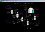
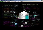
Instrumentation
The motor for P-301 is operated by switch HS-301. The hydrolyzate flow rate to F-301 is controlled by controller FIC-301. The water, ammonia and cellulase feed flows are controlled by controllers FIC-302, FIC-303 and FIC-304, respectively. Each of these controllers can be operated in cascade/ratio control to the flow rate of FIC-301 by placing them into cascade mode.
Note that a selector switch, HS-301R, is present on page 2 of the group and trend displays. When this switch is in the AUTO position, the ratio of FIC-302, FIC-303 and FIC-304 will be automatically set when these controllers are not in cascade mode to provide bumpless transfer when switched into cascade mode. If HS-301R is in the MAN position, the operator must adjust the ratio manually from detail display of the controller before placing the controller into cascade mode, or leave the controllers in automatic mode and adjust the setpoints manually.
The flow rate of cleaning solution to F-301 is controlled by FIC-300. When cleaning F-301, the solution should initially be routed to the disposal facilities using HIC-302. Once F-301 is clean, the solution from F-301 can be pumped to T-301 via FIC-307 for cleaning the downstream equipment and lines.
The level of F-301 is indicated on LI-301. The operator must manually adjust inflows and outflows of F-301 to avoid overfilling it or to avoid operation of P-302 with a low liquid level in F-301. Overfilling F-301 will result in liquid carryover to the atmospheric vent line and should be avoided. Operation of P-302 with a low liquid supply level can result in damage to the pump.
The motor of the agitator for F-301 is operated by switch HS-304. It should not be operated whenever there is not a measurable liquid level in F-301.
The temperature of F-301 is controlled by controller TIC-303 which adjusts the flow of cooling water through the coils within F-301.
The concentration of the cellulase enzymes in F-301 is indicated on AI-301.
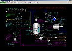
The motor of Air Blower K-301 is operated by switch HS-306. The outlet temperature of Air Cooler E-301 is controlled by TIC-308 which adjusts the cooling water flow through E-301.
The flow rate of air to F-301 is controlled by FIC-305. The air flow through K-301 is kept from going below a minimum flow of 18,000 SCFMXXX SM3/H by controller FIC-306.
The motor of Cellulase Transfer Pump P-302 is operated by switch HS-302. The cellulase transfer flow rate to T-301 is controlled by FIC-307. The manual control valve from P-302 to the disposal facilities is controlled by HIC-302. The flow in this line is not metered.