
Process Description
Simtronics’ Ethanol Plant simulator enables comprehensive training for ethanol plant operators. The simulator consists of two connected processing units: Biomass Fermentation and Ethanol Distillation.
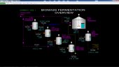
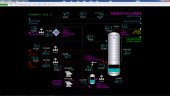
Biomass Fermentation Unit
The simulated Biomass Fermentation process is representative of new processes that employ Simultaneous Saccharification and Co-Fermentation (SSCF). The simulated process includes three fermenters which are used to:
- Grow cellulase (an enzyme that converts feed cellulose to sugars)
- Grow the inoculum Z. mobilis (a seed that converts sugars to ethanol)
- Simultaneously convert cellulose to sugars and produce ethanol
These three fermenters allow operators to develop a good understanding of fermentation principles and operations that would be applicable to commercial ethanol production facilities using a biomass feedstock.
Ethanol Distillation Unit
The simulated Ethanol Distillation unit is representative of the basic two-stage distillation process to conventionally concentrate the ethanol in a beer feed to approximately 95 liquid volume %. To make a fuel-grade ethanol product, the distillation section is followed by a drying unit to eliminate most of the remaining water in the product ethanol produced by distillation of the feed beer. The simulated process includes the following main equipment:
- Beer Column (to do the primary separation of ethanol from the beer)
- Rectification Column (to eliminate most of the water from the ethanol)
- Stillage Flash Drum (to remove ethanol from produced stillage)
- Ethanol Drying Unit (to eliminate additional water from the ethanol)
- Fusel Oil Decanter Unit (to remove byproduct fusel oils)
The conventional two-column distillation process allows operators to develop a good understanding of ethanol distillation principles and operations that would be applicable to commercial ethanol production facilities. This includes developing and understanding of the thermodynamic limit of ethanol concentration using conventional distillation.
Simulator Application
A full range of operations can be learned and practiced on the Ethanol Plant simulator. These include normal, startup, shutdown, and emergency shutdown procedures. The fermenters can be operated in either batch or continuous mode. This helps the operator understand why commercial processes employ many parallel trains that operate on a staged schedule so as to produce a near-continuous, high ethanol concentration product.
Instrumentation
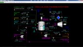
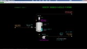
Cellulase Fermentation
The motor for P-301 is operated by switch HS-301. The hydrolyzate flow rate to F-301 is controlled by controller FIC-301. The water, ammonia and cellulase feed flows are controlled by controllers FIC-302, FIC-303 and FIC-304, respectively. Each of these controllers can be operated in cascade/ratio control to the flow rate of FIC-301 by placing them into cascade mode.
Note that a selector switch, HS-301R, is present on page 2 of the group and trend displays. When this switch is in the AUTO position, the ratio of FIC-302, FIC-303 and FIC-304 will be automatically set when these controllers are not in cascade mode to provide bumpless transfer when switched into cascade mode. If HS-301R is in the MAN position, the operator must adjust the ratio manually from detail display of the controller before placing the controller into cascade mode, or leave the controllers in automatic mode and adjust the setpoints manually.
The flow rate of cleaning solution to F-301 is controlled by FIC-300. When cleaning F-301, the solution should initially be routed to the disposal facilities using HIC-302. Once F-301 is clean, the solution from F-301 can be pumped to T-301 via FIC-307 for cleaning the downstream equipment and lines.
The level of F-301 is indicated on LI-301. The operator must manually adjust inflows and outflows of F-301 to avoid overfilling it or to avoid operation of P-302 with a low liquid level in F-301. Overfilling F-301 will result in liquid carryover to the atmospheric vent line and should be avoided. Operation of P-302 with a low liquid supply level can result in damage to the pump.
The motor of the agitator for F-301 is operated by switch HS-304. It should not be operated whenever there is not a measurable liquid level in F-301.
The temperature of F-301 is controlled by controller TIC-303 which adjusts the flow of cooling water through the coils within F-301.
The concentration of the cellulase enzymes in F-301 is indicated on AI-301.
The motor of Air Blower K-301 is operated by switch HS-306. The outlet temperature of Air Cooler E-301 is controlled by TIC-308 which adjusts the cooling water flow through E-301.
The flow rate of air to F-301 is controlled by FIC-305. The air flow through K-301 is kept from going below a minimum flow of 18,000 SCFM by controller FIC-306.
The motor of Cellulase Transfer Pump P-302 is operated by switch HS-302. The cellulase transfer flow rate to T-301 is controlled by FIC-307. The manual control valve from P-302 to the disposal facilities is controlled by HIC-302. The flow in this line is not metered.
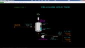
Cellulase Hold Tank
The level of T-301 is indicated on LI-302. The operator must manually adjust inflows and outflows of T-301 to avoid overfilling it or to avoid operation of P-303 with a low liquid level in T-301. Overfilling T-301 will result in liquid carryover to the atmospheric vent line and should be avoided. Operation of P-303 with a low liquid supply level can result in damage to the pump.
The temperature of T-301 is indicated on TI-304. Unexpected increase of this temperature likely indicates reaction(s) are occurring in T-301 (e.g. saccharification) or there are excessive shear forces on the agitator.
The motor of the agitator for T-301 is operated by switch HS-305. It should not be operated whenever there is not a measurable liquid level in T-301.
The motor of Cellulase Pump P-303 is operated by switch HS-303. The flow rate through the pump is set by flow controllers FIC-314 at SSCF Seed Fermenter F-311 and FIC-322 at SSCF Fermenter F-321.
The concentration of the cellulase enzymes in the discharge line of P-303 is indicated on AI-302.
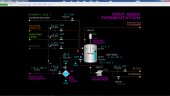
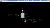
SSCF Seed Fermentation
The hydrolyzate flow rate to F-311 is controlled by controller FIC-311. The inoculum, corn steep liquor and cellulase feed flows are controlled by controllers FIC-312, FIC-313 and FIC-314, respectively. Each of these controllers can be operated in cascade/ratio control to the flow rate of FIC-311 by placing them into cascade mode.
Note that a selector switch, HS-311R, is present on page 6 of the group and trend displays. When this switch is in the AUTO position, the ratio of FIC-312, FIC-313 and FIC-314 will be automatically set when these controllers are not in cascade mode to provide bumpless transfer when switched into cascade mode. If HS-311R is in the MAN position, the operator must adjust the ratio manually from detail display of the controller before placing the controller into cascade mode, or leave the controllers in automatic mode and adjust the setpoints manually.
The temperature of the hydrolyzate feed to the SSCF Seed Fermenter is controlled by TIC-312 which adjusts the cooling water flow through Feed Cooler E-311.
The flow rate of cleaning solution to F-311 is controlled by FIC-310. When cleaning F-311, the solution should initially be routed to the disposal facilities using HIC-311. Once F-311 is clean, the solution from F-311 can be pumped to T-311 via FIC-315 for cleaning the downstream equipment and lines.
The level of F-311 is indicated on LI-311. The operator must manually adjust inflows and outflows of F-311 to avoid overfilling it or to avoid operation of P-311 with a low liquid level in F-311. Overfilling F-311 will result in liquid carryover to the exhaust gas scrubber and should be avoided. Operation of P-311 with a low liquid supply level can result in damage to the pump.
The motor of the agitator for F-311 is operated by switch HS-313. It should not be operated whenever there is not a measurable liquid level in F-311.
The temperature of F-311 is controlled by controller TIC-313 which adjusts the flow of cooling water through the coils within F-311.
The concentration of the SSCF seed in F-311 is indicated on AI-311.
The motor of SSCF Seed Transfer Pump P-311 is operated by switch HS-311. The cellulase transfer flow rate to T-311 is controlled by FIC-315. The manual control valve from P-311 to the disposal facilities is controlled by HIC-311. The flow in this line is not metered.
SSCF Seed Hold Tank
The level of T-311 is indicated on LI-312. The operator must manually adjust inflows and outflows of T-311 to avoid overfilling it or to avoid operation of P-312 with a low liquid level in T-311. Overfilling T-311 will result in liquid carryover to the exhaust gas scrubber and should be avoided. Operation of P-312 with a low liquid supply level can result in damage to the pump.
The temperature of T-311 is indicated on TI-314. Unexpected increase of this temperature likely indicates reaction(s) are occurring in T-311 (e.g. saccharification) or there are excessive shear forces on the agitator.
The motor of the agitator for T-311 is operated by switch HS-314. It should not be operated whenever there is not a measurable liquid level in T-311.
The motor of SSCF Seed Pump P-312 is operated by switch HS-312. The flow rate through the pump is set by flow controller FIC-323 at SSCF Fermenter F-321.
The concentration of the SSCF Seed in the discharge line of P-312 is indicated on AI-312.
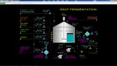
SSCF Fermentation
The hydrolyzate flow rate to F-321 is controlled by controller FIC-331. The cellulase, SSCF seed, corn steep liquor and ammonia feed flows are controlled by controllers FIC-322, FIC-323, FIC-324 and FIC-325, respectively. Each of these controllers can be operated in cascade/ratio control to the flow rate of FIC-321 by placing them into cascade mode.
Note that a selector switch, HS-321R, is present on page 9 of the group and trend displays. When this switch is in the AUTO position, the ratio of FIC-322, FIC-323, FIC-324 and FIC-325 will be automatically set when these controllers are not in cascade mode to provide bumpless transfer when switched into cascade mode. If HS-321R is in the MAN position, the operator must adjust the ratio manually from detail display of the controller before placing the controller into cascade mode, or leave the controllers in automatic mode and adjust the setpoints manually.
The temperature of the hydrolyzate feed to the SSCF Fermenter is controlled by TIC-321 which adjusts the cooling water flow through Feed Cooler E-321.
The flow rate of cleaning solution to F-321 is controlled by FIC-320. When cleaning F-321, the solution should initially be routed to the disposal facilities using HIC-321. Once F-321 is clean, the solution from F-321 can be pumped to T-321 via FIC-327 for cleaning the downstream equipment and lines.
The level of F-321 is indicated on LI-321. The operator must manually adjust inflows and outflows of F-321 to avoid overfilling it or to avoid operation of P-321A/B with a low liquid level in F-321. Overfilling F-321 will result in liquid carryover to the exhaust gas scrubber and should be avoided. Operation of P-321A/B with a low liquid supply level can result in damage to the pump.
The motor of the agitator system for F-321 is operated by switch HS-323. It should not be operated whenever there is not a measurable liquid level in F-321.
The temperature of F-321 is indicated by TI-322 on the line to the suction of pumps P-321A/B. The circulating beer return temperature is controlled by TIC-323 which adjusts the flow of chilled cooling water through the heat exchanger E-322. If the temperature of F-321 becomes too low or too high, adjust the circulating beer flow rate through E-322 using FIC-326.
The concentration of the ethanol in F-321 is indicated on AI-321.
The motor of SSCF Circulation & Transfer Pumps P-321A/B are operated by switches HS-321A/B. The beer transfer flow rate to T-321 is controlled by FIC-327. The manual control valve from P-321A/B to the disposal facilities is controlled by HIC-321. The flow in this line is not metered.
Beer Storage Tank
The level of T-321 is indicated on LI-322. The operator must manually adjust inflows and outflows of T-321 to avoid overfilling it or to avoid operation of P-322 with a low liquid level in T-321. Overfilling T-321 will result in liquid carryover to the exhaust gas scrubber and should be avoided. Operation of P-322 with a low liquid supply level can result in damage to the pump.
The temperature of T-321 is indicated on TI-324. Unexpected increase of this temperature likely indicates reaction(s) are occurring in T-321 (e.g. saccharification and/or ethanol production) or there are excessive shear forces on the agitator.
The motor of the agitator for T-321 is operated by switch HS-334. It should not be operated whenever there is not a measurable liquid level in T-321. The motor of Beer Pump P-322 is operated by switch HS-322. The flow rate through the pump is set by flow controller FIC-328. The concentration of the ethanol in the discharge line of P-322 is indicated on AI-322.
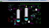
Beer Column
The beer feed to the unit from battery limits is controlled by FIC-328 in the fermentation section. It is also indicated on FI-501 in the distillation section. The beer ethanol concentration is indicated on AI-501 and the temperature is indicated on TI-501. After passing through E-502 and E-501, the preheated beer temperature is indicated on TI-503 prior to entering the Beer Column T-501.
The top pressure of T-501 is indicated on PI-501 and the overhead vapor temperature is indicated TI-504. Tray 20’s temperature is indicated on TI-505. The differential pressure across the trays of the Beer Column is indicated on PDI-503. The bottom level of stillage in T-501 is controlled by LIC-501 which adjusts the flow of stillage to the Stillage Flash Drum D-501. The stillage temperature from T-501 is indicated on TI-506. Direct LP steam flow to the bottom of T-501 is controlled by FIC-503. The supply pressure of LP steam is indicated on PI-503.
The level of stillage in the Stillage Flash Drum D-501 is controlled by LIC-502 which adjusts the flow of stillage to storage at battery limits. The flow rate of MP steam to the Stillage Flash Ejector EJ-501 is controlled by FIC-504. The supply pressure of MP steam is indicated on PI-504. The pressure of the Stillage Flash Drum is indicated on PI-502. This pressure is affected by the net vapor compression capacity of EJ-501 which is, in turn, affected by the MP steam flow to the ejector. Therefore, adjustments to the MP steam flow will affect the pressure in D-501. Keep in mind that any MP steam flow adjustments will also affect the performance of the distillation columns (e.g. more steam will eventually increase the ethanol concentration in the vapor to the drying unit and will increase the reflux in the two columns). The motors for Stillage Pumps P-501A/B are operated by switches HS-501A/B, respectively. The warm stillage temperature leaving P-501A/B is indicated on TI-507. The temperature of stillage after cooling in E-501 is indicated on TI-508. The flow rate of stillage to storage at battery limits is indicated on FI-502.
Rectification Column
The ethanol concentration of the vapor feed to the Rectification Column T-502 from the Beer Column T-501 is indicated on AI-502. The level of the bottom of T-501 is controlled by LIC-511 which adjusts the setpoint of the column bottoms liquid flow controller FIC-511. Rectification Column bottoms is reflux for the Beer Column T-501. The T-502 bottoms liquid temperature is indicated on TI-515. The ethanol composition of the bottoms liquid is indicated on AI-511.
The motors for Rectification Column Bottoms Pumps P-502A/B are operated by switches HS-502A/B, respectively. The flow of column bottoms from P-502A/B to Beer Column T-501 is controlled by FIC-511.
The differential pressure across the trays of T-502 is indicated on PDI-512. The flow of the upper side draw to the Fusel Oil Decanter X-502 is controlled by HIC-511. The upper draw tray temperature is indicated on TI-513. The flow of the lower side draw to the Fusel Oil Decanter X-502 is controlled by HIC-512. The lower draw tray temperature is indicated on TI-514. The wash water flow to X-502 is controlled by FIC-512. The net produced fusel oil product flow to battery limits is indicated on FI-513.
The temperature of tray 28 is controlled by TIC-512 which adjusts the cooling water flow through Condenser E-503. Increasing the cooling water flow will produce more condensate from E-503 which, in turn, will cause the reflux flow to the top of T-502 to increase. As the reflux flow increases, the temperature of tray 28 will decrease because the tray’s ethanol concentration will increase at the expense of the water concentration.
The pressure at the top of T-502 is indicated on PI-511. The overhead vapor temperature entering Beer Preheater No. 1 E-502 is indicated on TI-511. The temperature of the partially condensed vapor leaving E-502 is indicated on TI-516. The beer feed temperature leaving E-502 is indicated on TI-502.
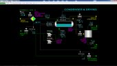
Condenser & Drying Section
The process side outlet temperature of Rectification Column Condenser E-503 is indicated on TI-521. The cooling water flow through E-503 is controlled by tray 28 temperature controller TIC-512. Note that TV-512 has a minimum stop of 10% to prevent complete stoppage of cooling water flow through E-503.
The pressure of Reflux Drum D-502 is normally controlled by PIC-521B which controls the flow of concentrated ethanol vapor to the Ethanol Drying Unit X-501. The flow of vapor to X-501 is indicated on FI-523 and the ethanol content of the vapor is indicated on AI-521. PIC-521A will automatically vent the ethanol vapor from D-502 if the pressure gets too high. Its setpoint is 20 PSIA.
The flow of product ethanol from X-502 is indicated on FI-524. The flow of recycle ethanol is indicated on FI-525.
The level of D-502 is normally controlled by LIC-521A which adjusts the setpoint of the Rectification Column reflux flow controller FIC-521. In case the level in D-502 gets too high, LIC-521B will divert wet ethanol from D-502 to storage at battery limits. The setpoint of LIC-521B is 90%.
The motors for Reflux Pumps P-503A/B are operated by switches HS-503A/B, respectively. The flow of reflux (wet ethanol) P-503A/B to Rectification Column T-502 is controlled by FIC-521. The concentration of ethanol in the reflux is indicated on AI-522 and the temperature of the reflux is indicated on TI-522. The flow rate of wet ethanol to storage at battery limits is controlled by FIC-522.