 |
 |
 |
|
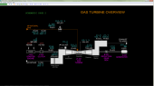
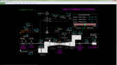
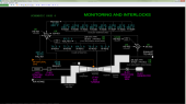
| Click to view schematic display A | Click to view schematic display B | Click to view schematic display C | |
Process Description
Simtronics’ Gas Turbine with Generator program represents a typical
gas turbine used for electric power generation. Unlike real industrial
units, the simulated gas turbine is managed by the operator instead of a
highly automated control system. This allows the operator to better
understand the basic principles of operation of a gas turbine.
Additionally, the gas turbine drives an electric generator connected to
a large, regional electric power grid. Simtronics’ Gas Turbine with
Generator simulator requires the operator to manually synchronize the
gas turbine/generator set with the electric grid before connecting to
it. This allows the operator to understand the concept of
synchronization and its importance in keeping the generator from being
damaged during connection to the electric power grid, since most real
industrial systems use an auto-synching device/system to connect a
generator to a power grid.
A full range of operations can be learned and practiced on the Gas
Turbine with Generator simulator. These include normal, startup,
shutdown, and emergency shutdown procedures.
Gas Turbine with Generator
The Gas Turbine with Generator program represents a typical gas
turbine/power generator unit found in a power plant. The gas turbine
uses compressed air and fuel gas to drive the expander of the Gas
Turbine which turns an electric power generator. The hot exhaust gas
from the gas turbine is sent to a Gas Turbine with Generator. Electric
power produced by the generator is delivered to a power grid for
distribution to electric power users.
Ambient air is pulled into the Intake Plenum of Gas Turbine JT-401. A
screen on the inlet of the plenum prevents larger objects from being
pulled into the plenum. A filter is installed in the plenum to remove
any smaller objects from reaching the Gas Turbine rotating equipment.
The filtered air is compressed in the Air Compressor section of JT-401.
The Intake Plenum and the Air Compressor are specially designed to
ensure even distribution of the air throughout the intake to the
compressor and into the Combustor Assembly. The Air Compressor is an
axial type and is fitted with inlet guide vanes which are essentially
louvers that can be used to restrict the air flow into the compressor if
needed. The angle of the guide vanes are positioned by actuator ZV-401.
Normally the guide vanes are nearly fully open (85%) but can be adjusted
during startup and shutdown and off-design ambient temperature operation
to give optimal air flow to the Combustor Assembly.
Hot air from the discharge of the Air Compressor enters the Combustor
Assembly at roughly 316 PSIG. This assembly consists of a specially
designed series of burners arranged radially. There are 10 burners. Each
burner set consists of two primary burners and one secondary burner. The
fraction of fuel gas distributed between the primary and secondary
burners is automatically controlled depending on load. This design
permits efficient combustion of fuel while minimizing nitrous oxide
(NOx) emissions.
The Combustor Assembly is designed to distribute air to the burners for
combustion and to use a portion of the air to cool critical parts of the
Gas Turbine near the burners. In order to avoid extremely high
combustion temperatures which would cause mechanical problems in the
Combustor Assembly and in the Expander, the Gas Turbine operates with a
fairly large excess of air for combustion. A significant fraction of
this excess air bypasses the burners and then remixes with hot gas from
the burners along the outlet assembly of the burner sets prior to
entering the Expander.
High pressure natural gas flow is regulated by the speed control system
with control valve SV-401 and is distributed into the 10 burners of the
Combustor Assembly. The split of fuel between the primary and the
secondary burners of the burner sets in the Combustor Assembly is
assumed to be ideal on the simulator. An automatic spark system and
flame sensors ensure combustion is safely maintained. Only two of the
burner sets are outfitted with spark plugs and every other set is
outfitted with a flame sensor. Crossfire tubes connect each burner set
laterally to ensure quick light-off of the other eight burners from an
adjacent burner. The Gas Turbine is designed for operation only on
natural gas; therefore, the burner sets do not include injection nozzles
to handle liquid fuels. Also, the staged combustion system does not
require the use of water injection to attain low NOx performance.
The high pressure, hot combustion gases from the outlets of the 10
burner sets are distributed evenly along the outside of the Expander
inlet. As hot gas flows through the wheels of the Expander it turns the
shaft which drives the Air Compressor and the Generator. As the gas
expands and does work on the wheels of the Expander it cools, leaving
the Expander at around 1,100 DEG F and near-atmospheric pressure. The
warm exhaust gas is collected in the Exhaust Plenum and routed to the
Heat Recovery Steam Generator (HRSG) prior to being exhausted to
atmosphere. Eight temperature sensors are radially distributed at the
Expander’s exhaust to detect any maldistribution of heat in the
Combustor Assembly.
The shaft of Gas Turbine JT-401 is connected to Reduction Gear Box B-401
which in turn is connected to the shaft of Generator G-401. The
Reduction Gear Box changes the shaft speed of the Gas Turbine by
one-half. Generator G-401 produces electric power which is sent to a
region-wide electric power grid. A breaker switch is provided to allow
connection and disconnection of Generator G-401 to/from the power grid.
Starter Engine J-401 is a diesel engine that provides power during
startup to turn the air compressor section of the Gas Turbine prior to
starting fuel gas to the combustor assembly. Clutch C-401 allows
engagement and disengagement of the shaft of the Start Engine J-401 with
the shaft of Gas Turbine JT-401. In normal operation J-401 is stopped
and C-401 is disengaged.
Instrumentation
Gas Turbine Controls and Instruments
The temperature of ambient air for combustion in Gas Turbine JT-401
is measured by TI-402 at the Intake Plenum entrance. The pressure
drop across the filter in the Intake Plenum is measured by PDI-402.
The position of the inlet guide vane of the Air Compressor of JT-401
is adjusted by ZIC-401. The discharge pressure of air leaving the
Air Compressor is measured by PI-402.
The natural gas flow to JT-401 is indicated on FI-401. The supply
pressure of natural gas is indicated on PI-401 and its temperature
is indicated on TI-401. Speed controller SIC-401 regulates the
opening of natural gas control valve SV-401.
The speed of the shaft of JT-401 is measured by SI-401. This
instrument is also used by the speed control system for JT-401. The
speed of JT-401, expressed as % of design speed (3,600 RPM), is
indicated on SIC-401. SIC-401 normally operates in cascade mode when
Generator G-401 is connected to the electric power grid. This
control mode is entered by placing droop control switch HS-403 into
the DROOP state. Droop control is explained in the next section.
SIC-401 can be taken out of droop/cascade control and placed in
automatic or manual mode. Automatic mode is used only at startup
when the generator is not connected to the grid. In this case,
SIC-401 directly controls the shaft speed. In manual mode, SIC-401
is used to manually adjust the fuel flow to JT-401. Manual mode of
SIC-401 is available any time the Gas Turbine is not tripped. Manual
mode is entered any time the droop control switch HS-403 is changed
from the DROOP to the OFF state.
For startup, switch HS-406 is used to start and stop the Starter
Engine J-401. SIC-405 is used to control the speed of the motor and
the Gas Turbine at startup. The starter engine is connected to the
shaft of the gas turbine by clutch C-401 which is engaged and
disengaged using switch HS-405. This switch should only be switched
to the ON state (engaged) when the Gas Turbine is not rotating to
avoid mechanical damage to the unit. The clutch can be disengaged at
any time.
The ignition system for the Gas Turbine is started by placing switch
HS-404 into the ON state. HS-404 should only be turned off when the
Gas Turbine is shut down. XAL-401 indicates the lowest burner
intensity reading from the Gas Turbine monitoring system (see
details of the monitoring system in the section about interlocks).
TAH-403 indicates the highest exhaust temperature from the
monitoring system. The oxygen content of the Gas Turbine exhaust is
indicated on AI-403. The pressure of the Gas Turbine exhaust plenum
is indicated on PI-403.
The shaft speed of Generator G-401 is indicated on SI-402. The power
output of G-401 is indicated on JI-420.
Generator G-401 is provided with a synchroscope in order to visually
see the difference of the frequency and phase between electricity
produced by G-401 and the electric grid at startup. Generator G-401
is connected to the electric power grid using switch HS-422. SI-420
indicates the frequency of electricity at the terminals of G-401.
SI-421 indicates the frequency of electricity of the electric grid
after the breaker switch. SI-422 indicates the phase difference
between electricity generated at the terminals of G-401 and the
electric grid. Before connecting the Generator to the grid with
breaker switch HS-422, the frequencies of the Generator must be the
same and the phase difference must be nearly zero. Otherwise, the
Generator may suffer major damage when the breaker switch is closed.
Droop Control
When any synchronous electric generator is connected to a large grid
in parallel with many other synchronous machines such as generators
and electric motors, a single generator cannot easily or reliably
control the frequency of the electric power of the grid because it
is only generating a small fraction of the total power being
consumed from the grid. In this case, the generator will run at the
grid speed or frequency. Therefore, the speed of the power turbine
that drives the generator cannot be controlled when the generator is
connected to a large grid.
The grid frequency dynamically depends directly on the balance of
power generation and consumption across the grid. If generators are
producing more power than the power consumers on the grid, the grid
frequency will increase, causing all synchronous motors connected to
the grid to speed up. As they speed up, they will consume more power
until the power consumption comes into balance with power
generation. In order for many generators to supply electricity to a
large grid, they cooperatively adjust their power output using what
is known as droop control.
Droop control simply proportions a generator’s power output to the
deviation between of the actual grid frequency and its setpoint
frequency (60 Hz). If the actual grid frequency is at the setpoint,
the generator will put out its design power. When the grid frequency
is higher than the setpoint, the generator will decrease its power
output in proportion to the deviation. Each generator system with
droop control is configured with a characteristic droop control
constant, expressed as % of setpoint speed. For JT-401/G-401 this
constant is 4%. At 4% overspeed of the grid (i.e. 62.452 Hz) the
droop controller will adjust the power output to the minimum stable
power operation for JT-401/G-401.
When SIC-401 is placed into droop mode using switch HS-403, the PV
of SIC-401 is computed as follows:
PV = [SI-421.PV * 60 + (SIC-401.OP - 25.0) * 3.3333] * 100/3,600
The setpoint of SIC-401 is locked at 104.0 when in droop mode. Any
deviation of the grid frequency (SI-421.PV) will cause SIC-401 to
move its output such that the PV is restored back to the setpoint of
104.0. The integral action of controller SIC-401 will cause the
output (and power) to move gradually.
Monitoring System
The monitoring system protects the Gas Turbine and Generator from
conditions that would damage them. This includes:
- low combustor flame intensity
- high expander exhaust temperature
- high turbine shaft speed
- gas turbine mechanical trouble
- generator mechanical trouble
There are separate interlock circuits for the Gas Turbine and the
Generator that use the monitoring systems. I-401 protects the Gas
Turbine and I-402 protects the Generator.
For the Gas Turbine, flame intensities are measure on indicators
XA-401A/B/C/D/E. The lowest of these flame intensities is selected by
indicator XAL-401. When XAL-401 gets below 10%, it will activate a trip
alarm which is used by interlock I-401.
Also, exhaust temperatures from the Gas Turbine are indicated on
TI-403A/B/C/D/E/F/G/H. The highest of these temperatures is selected by
indicator TAH-403. When TAH-403 exceeds 1,200 DEG F, it will activate a
trip alarm which is used by interlock I-401.
SAH-401 indicates the Gas Turbine shaft speed independently of SI-401
used for the speed control system. When SAH-401 exceeds 4,000 RPM it
will activate a trip alarm which is used by interlock I-401.
Any problems with the mechanical systems of JT-401 (not simulated in
detail) will be alarmed on XI-411. If the problem becomes worse or
another serious mechanical problem with JT-401 occurs, it will cause
XA-411 to alarm. XA-411 is used by interlock I-401.
Any problems with the mechanical systems of G-401 (not simulated in
detail) will be alarmed on XI-421. If the problem becomes worse or
another serious mechanical problem with G-401 occurs, it will cause
XA-421 to alarm. XA-421 is used by interlock I-402.
Interlock I-40
Interlock I-401 protects the Gas Turbine from flame-out, overheating,
overspeed and mechanical problems. I-401 activates on any of the
following inputs:
- XAL-401 (low burner intensity)
- TAH-403 (high exhaust temperature)
- SAH-401 (high shaft speed)
- XA-411 (mechanical trouble such as low lube oil pressure, vibration, etc.)
- I-402 (Generator interlock)
- HS-401 (hand trip of Gas Turbine)
XAL-401’s signal is a one-shot signal to allow a reset of I-401 when
there is no fuel to the unit. HS-401 serves as both a trip and reset
switch. All other trip inputs except for XAL-401 must be cleared in
order to reset I-401.
When I-401 trips, the following actions occur:
- XA-401 alarms
- SIC-401 is locked in manual mode and its output set to 0.0 to stop natural gas flow to the Gas Turbine
- Droop control switch HS-403 is locked in the OFF state
- Engine clutch switch HS-405 is locked in the OFF state
- Engine switch HS-406 is locked in the STOP state
- Breaker switch HS-422 is set to the OPEN state (note that this action does not trip I-402)
Interlock I-402
Interlock I-402 protects the Generator from damage when
disconnected from the grid and from mechanical problems. I-402 activates
on any of the following inputs:
- Opening of breaker switch HS-422 (if I-401 is not tripped)
- XA-421 (mechanical trouble such as electrical system problems, vibration, etc.)
- HS-402 (hand trip of Generator)
HS-422’s signal is a one-shot signal to allow a reset of I-402 when
restarting. HS-402 serves as both a trip and reset switch. Trip input
XA-421 must be cleared in order to reset I-402.
When I-402 trips, the following actions occur:
- XA-402 alarms
- I-401 (Gas Turbine trip) is activated