 |
 |
 |
|
| Click to view schematic display A | Click to view schematic display B | Click to view schematic display C | |
Process Description
Simtronics’ Boiler Feedwater System simulator represents a typical
boiler feedwater system found in facilities that generate steam such as
process plants, utility boilers and power plants. Boiler water
circulates in a mostly closed cycle from the Deaerator to boilers and
then to steam users. Most of the steam condensate from the steam users
is returned back to the Deaerator. Makeup water from battery limits is
brought in to replace lost water from the system. The Deaerator uses low
pressure steam from battery limits to strip any dissolved air or other
gases that may have been picked up in the system.
Deaerated boiler water is pumped to high pressure by the Boiler
Feedwater Pumps to supply boilers at their operating pressures. The
boilers supply steam to the users. The boilers and steam users are not
modeled in detail.
A full range of operations can be learned and practiced on the Boiler
Feedwater System simulator. These include normal, startup, shutdown, and
emergency shutdown procedures.
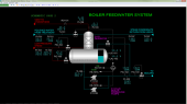
Boiler Feedwater System
Polished makeup water from battery limits is sent to the top of
the stripping section of Deaerator D-101 where it combines with warm
steam condensate returned from steam users. The stripping section of
D-101 is filled with structured packing to ensure good mixing of
deaeration steam and water. Low pressure steam from battery limits is
injected to the base of the stripping section of D-101. Enough steam is
added to the Deaerator to produce a small flow of steam from the top of
D-101 through restriction orifice RO-101. Stripping steam is added at
the base of the stripping section and warming steam is sparged into to
the water in the reserve base of D-101. A flow of steam through RO-101
ensures any dissolved oxygen and other gases are removed from the makeup
and recirculated steam condensate and vented from the system. Oxygen is
particularly undesirable in high pressure boiler service because it
leads to corrosion of the steam generating equipment.
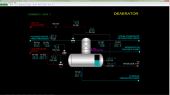
Stripping steam warms up the feed water to approximately the boiling
point of water at the pressure in the Deaerator. The Deaerator normally
operates slightly above atmospheric pressure. Water low in dissolved
oxygen falls from the stripping section into the bottom section of the
Deaerator which serves as a reserve volume of boiler water for the
system.
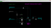
Boiler Feed Water Pumps P-101A/B are high head, multi-stage centrifugal
pumps and take suction from the bottom of D-101. Normally only one pump
is in operation. The pumps supply deaerated boiler feedwater to the
boilers in the system. To protect the pumps against being run
blocked-in, a minimum flow line from the discharge line of the pumps
back to D-101 is provided.
Instrumentation
Deaerator
Polished water from battery limits is controlled by LIC-101 to maintain
the level in the base of Deaerator D-101. The flow of polished water is
indicated on FI-101. The pressure and temperature of the polished water
are indicated on PI-101 and TI-101, respectively.
Low pressure (LP) steam flow from battery limits to the sparger of the
stripping section of the Deaerator is controlled by FIC-104. The flow of
LP steam to the sparger in the base of the Deaerator is controlled by
FIC-105. The pressure and temperature of the steam are indicated on
PI-104 and TI-104, respectively.
The pressure of the Deaerator is indicated by PI-103. Steam flow from
the overhead of the Deaerator is indicated on FI-106 before passing
through restriction orifice RO-101.
The flow of steam condensate returning from the steam users at battery
limits is indicated on FI-107. The temperature of the returning
condensate is indicated on TI-107. The flow of this condensate is
normally 88.8% of the boiler feedwater supplied by the Boiler Feedwater
System to the boilers at battery limits.
The level of water in the base of the Deaerator is also indicated on
LAH-102 which is used by Interlock I-101 (see below) to protect the
Boiler Feedwater Pumps against operating when there is excessively low
water level.
Boiler Feedwater Pumps
Switch HS-101A operates the motor of Boiler Feedwater Pump P-101A and
switch HS-101B operates P-101B. These switches are locked in the STOP if
interlock I-101 is tripped as indicated on switch XA-101. XA-101 is an
indicate-only switch.
FIC-103 controls the flow of boiler feedwater to the boilers at battery
limits. FIC-102 controls the amount of boiler feedwater passing through
pumps P-101A/B to a minimum flow in case the demand for water to the
boilers is low. This helps protect the high-head pumps against damage at
low-flow conditions due to high temperatures and cavitation/vibration.
The pressure of the discharge header of the pumps is indicated on
PI-102.
Interlock I-101
Interlock I-101 protects the Boiler Feedwater Pumps P-101A/B from
running in case of low level in the base of the Deaerator. I-101
activates if the level of LAL-102 is less than 10%. I-101 will remain
active anytime LAL-102 is less than 10% and will stop and lock the
motors of P-101A/B in the STOP state. I-101 will automatically reset
when higher than 10%. However, P-101A/B must be manually restarted after
the interlock resets. The interlock status is indicated on XA-101.