 |
 |
 |
 |
| Click to view schematic display A | Click to view schematic display B | Click to view schematic display C | Click to view schematic display D |
 |
|||
| Click to view schematic display E | |||
Process Description
Simtronics’ Multistage Flash Evaporator (MSF) process produces potable water from seawater. The seawater is provided from battery limits. Potable water is produced from the successive flashing (evaporation) and condensing of preheated seawater. This produces very pure water with a very low salt concentration. The salt water is returned to the sea.
Simtronics’ Multistage Flash Evaporator simulator consists of 3 flash/condensing cells. The water levels, temperature and pressure of each stage are indicated so that the principles of stage operation and interactions between stages can be demonstrated to the operator. Real commercial units often employ more than 20 cells, but the operating principles are still the same. The MSF simulator represents a once-through process so that the basic principles of the MSF process may be demonstrated without the added complexity of the recycle process.
A full range of operations can be learned and practiced on the Multistage Flash Evaporator simulator. These include normal, startup, shutdown, and emergency shutdown procedures.
Heat Recovery Steam Generator
Seawater is filtered in Seawater Filters F-101A/B. These are cartridge filters designed to remove any suspended solids from the feed water. Suspended solids can easily plug and foul the Multistage Flash Unit. Either filter cartridge can be taken out of service for maintenance.
Filtered feed water from F-101A/B is pumped to Multistage Flash Unit X-101 by Seawater Pumps P-101A/B. Normally only one pump is in operation.
In the Multistage Flash Unit X-101, the feed seawater is preheated from ambient temperature to 194 degrees Fahrenheit in a series of three evaporator/condenser stages. The preheated seawater is further heated in Seawater Heater E-101 using low pressure steam as the heat source.
The heated seawater from E-101 enters the base of the first evaporator stage of X-101 which operates at modest vacuum. As a result, a portion of the heated seawater flashes and produces nearly pure water vapor. The flashed water vapor rises through a mesh screen to eliminate moisture and then contacts the condenser at the top of the first flash stage. The water vapor condenses and is collected below the condenser tubes. The collected condensate is channeled to the condensate compartment of the next evaporator stage.
The vapor spaces of each evaporator stage are separated by baffles under which the heated seawater flows due to the pressure differential between each stage. The water level within each stage stays high enough to seal each vapor space from the adjacent ones. The baffle geometry is engineered to maintain vapor sealing under a variety of conditions and flow rates.
The evaporator stages operate at successively lower pressures. A pressure differential is developed between each stage due to the successively lower condenser temperature of each stage. Thermodynamic equilibrium between liquid and vapor water dictates that the lower the condenser temperature, the lower the pressure of the stage will be. The decreasing condenser temperature profile in each successive stage occurs because the feed seawater is counter currently preheated relative to the movement of seawater through the evaporator stages.
The condensed water vapor from each stage is collected in the upper condensate compartment of the final stage and routed to Water Transfer Pumps P-102A/B to transfer the purified water to Purified Water Tank T-101. Normally, only one pump is in operation. Because the product water has been distilled, it contains very low concentrations of salt and other impurities, making it suitable for drinking and industrial use.
The brine, which is rejected from the base of the last evaporator stage of X-101, is routed to Reject Brine Pumps P-103A/B for disposal at battery limits. Normally only one pump is in operation.
The purified water is pumped from T-101 to distribution by Purified Water Pumps P-104A/B. Normally only one pump is in service.
Prior to distribution, the purified water is further filtered in Cartridge Filter F-102 to remove any solid particles and in Activated Carbon Filter F-103 to remove any trace organic compounds that may have entered the unit. Either product filter can be bypassed for maintenance.
Instrumentation
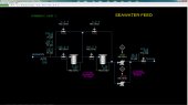
Seawater Feed
The temperature of the seawater feed is indicated on TI-101, the pressure is indicated on PI-101 and the flow rate is indicated on FI-101. AI-101 indicates the conductivity of the seawater feed in S/m units (siemens per meter). The conductivity depends on the salt concentration of the seawater.
PDI-101A and PDI-101B indicate the pressure drop across the seawater filters F-101A/B. HIC-101A and HIC-101C control the block valves of the seawater filters F-101A/B. HIC-101B and HIC-101D control the bypass valves of the seawater filters F-101A/B.
The status of the seawater pumps P-101A/B is indicated on switches HS-101A/B, same switches can be used to start/stop the pumps. The discharge pressure of seawater pumps P-101A/B is indicated on PI-102.
The seawater flow from battery limits to the Multistage Flash Unit X-101 is controlled by FIC-102.
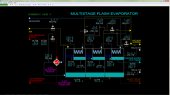
Multistage Flash Evaporator
The Multistage Flash Unit X-101 consists of three stages. The seawater feed enters the third stage condenser coil. The temperature at the outlet of the condenser of the third stage is indicated on TI-110. TI-111 indicates the temperature at the outlet of the condenser of the second stage and TI-112 indicates the temperature at the outlet of the condenser of the first stage. PIC-110, PIC-111 and PIC-112 control the pressure of the first, the second and the third stage of the Multistage Flash Unit X-101, respectively, from becoming too high by evacuating vapor to the vacuum system. Normally, there is no flow to vacuum system because the vapor space is pure water and the pressure of the cell is effectively determined by the temperature of the condenser.
LI-110 and LI-111 indicate the level of the first and second upper condensate compartments while LI-113 and LI-114 indicate the level of the first and second lower compartments of evaporator X-101. LIC-112 controls the level of the third upper condensate compartment and LIC-115 controls the level of the third lower compartment.
TI-113, TI-114 and TI-115 indicate the temperature of the vapor which is routed to the condensers of the first, the second and the third stages of the Evaporator unit X-101, respectively. TI-116 indicates the temperature of the purified water which exits from the upper condensate compartment of the third stage.
The heating medium of the seawater heater E-101 is low pressure steam. The flow rate and the supply pressure of the steam are indicated on FI-105 and PI-106, respectively. TIC-105 controls the temperature of the heated seawater which enters the base of the first evaporator stage of X-101.
Finally HIC-102 controls the flow of ambient air used to break vacuum in the unit. The air enters at the first stage of the Multistage Flash Unit X-101. HIC-102 is normally closed.
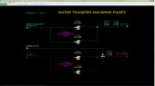
Water Transfer and Brine Pumps
The status of the water transfer pumps P-102A/B is indicated on switches HS-102A/B, same switches can be used to start/stop the pumps. The discharge pressure of transfer water pumps P-102A/B is indicated on PI-120 while the flow rate of the distillate water through these pumps is indicated on FI-120.
The status of the reject brine pumps P-103A/B is indicated on switches HS-103A/B, same switches can be used to start/stop the pumps. The flow rate of the brine through the reject brine pumps P-103A/B is indicated on FI-122.
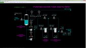
Purified Water Tank and Filters
LI-120, LAH-120 and LAL-120 indicate the water level in the purified water tank T-101. LAH-120 and LAL-120 are also connected to interlocks which are activated in case of high or low level respectively in T-101.
The status of the purified water pumps P-104A/B is indicated on switches HS-104A/B, same switches can be used to start/stop the pumps. The discharge pressure of purified water pumps P-104A/B is indicated on PI-121.
PDI-120 and PDI-121 indicate the pressure drop across the cartridge filter F-102 and the activated carbon filter F-103, respectively. HIC-120A controls the block valve of the cartridge filter F-102 while HIC-120C controls the block valve of the activated carbon filter F-103. HIC-120B controls the bypass valve of the cartridge filter F-102 and HIC-120D controls the bypass valve of the activated carbon filter F-103.
FIC-121 controls the flow rate of the produced purified water to the users. The temperature of the produced purified water is indicated on TI-120. AI-120 indicates the conductivity of the purified water in mS/m units (103 mS/m = 1 S/m).