Process Description
Overview of Advanced MSF
Simtronics’ Advanced Multistage Flash (MSF) Evaporator simulator represents a typical commercial distilled water production unit that produces potable water from sea water. The simulator consists of:
- 24-stage Evaporator (MSF) Unit
- Integrated Deaerator
- Main Brine Heater
- Brine Recirculation Pump
- Distillate Pump
- Heater Drain Pump
- Brine Blowdown Pump
- Sea Water Recirculation Pump
- Sea Water Supply Pumps
- Vacuum System
- Condensate System for the Main Brine Heater
- Chemical Injection Tanks and Pumps
- Cooling Water System
- Sump Pit and Sump Pumps
- Ball Cleaning System
- Instrument Air System
Sea water is provided from battery limits to the Sea Water Supply Pumps, P-201 I/J/K/L. Potable water is produced from the successive flashing (evaporation) and condensing of preheated seawater in the Evaporator, HX-101. This produces very pure water with a very low salt concentration. The salt water (brine) is returned to the sea.
The Evaporator unit consists of 24 cells in which circulating brine is flashed (partially vaporized) under vacuum conditions. The flashed water vapor is condensed in each cell to produce a very pure distillate product.
The first 21 stages use circulating brine as the coolant for the condenser in each cell. This is known as the heat recovery section of the Evaporator. Brine is sea water that has an increased salt concentration from the evaporation of water in the cells. By circulating brine, the process is made more energy efficient compared to a once-through processing scheme of the sea water.
The circulating brine heats up as it passes through the condensers in stage 21 through stage 1. The warm brine is then heated with steam in the Main Brine Heater,HX-102 and fed directly into stage 1 where water vapor flashes off owing to its higher temperature and vacuum conditions which allow the brine to boil at a lower temperature than at atmospheric pressure.
The flashed water vapor condenses in the condenser tubes located in the upper section of the cell and is collected as distillate in pans below the condenser tubes. Both the brine and the distillate flow separately from stage 1 to stage 24, creating more distillate in each cell because of the successively lower vacuum pressure between cell 1 and cell 24.
Specially designed channels and baffles allow the distillate and brine to flow from cell to cell while sealing each cell’s vapor space from the adjacent cells. Each cell establishes its own pressure based on the vapor pressure of the distillate (pure water) formed in the cell. The temperature of the distillate depends on the temperature of the brine and cooling sea water fed to the cell’s condenser.
The last 3 stages of the Evaporator, known as the heat rejection section, use sea water as coolant for their condensers. Fresh, cool sea water is brought in to the condenser tubes of stages 24, 23 and 22. The sea water is heated before returning to the sea, exhausting heat from the Evaporator. A portion of the heated sea water is taken as feed to the circulating brine system.
The sea water feed is first deaerated in the Deaerator, DA-101 using vacuum to remove most of the dissolved gases in the sea water. The deaerated feedwater passes from the Deaerator into stage 24 where it combines with the circulating brine. Excess brine is taken off from stage 24 and discharged to the sea. In case the sea water temperature is cool, a portion of the heated sea water from stage 22’s condenser can be recirculated back to stage 24 in order to keep distillate temperatures from becoming too cool.
Distillate produced by the Evaporator is collected in a well built into the Evaporator after stage 24. The distillate is pumped from the well to storage for distribution. The pumped distillate is used as coolant for the condensers, HX 301, HX-103, and HX-104, in the vacuum system. At low distillate flow rates, a portion of the warm distillate from the condensers is recirculated back to stage 22, where a portion of it will flash and recondense when cooled by circulating sea water in the condenser coils of stages 22 through 24.
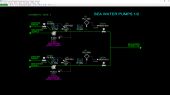
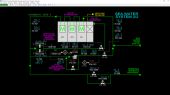
Sea Water Pumps
The Sea Water Supply Pumps P-201I/J/K/L are motor-driven centrifugal pumps that take suction from the sea water supply line at battery limits. Sea water contains 3.5 weight percent dissolved salts. Normally 2 pumps are in operation.
The pumps supply water to the Evaporator, HX-101, to the Service Cooling Water System and to the Vent Gas Condenser, HX-105. The normal flow rate of each pump is 28,583 GPM (41.16 MGD)12,671 M3/H (12,962 T/H). The discharge pressure of each pump is normally 41.9 PSIG2.89 BARG. The normal temperature of the sea water is 81.7 DEG F27.6 DEG C.
The discharge sea water from P-201I and P-201J combine after passing through their respective discharge MOVs and are sent to the Debris Filter, STR-103. The combined sea water discharge from P-201K and P-201L is routed to the line downstream of STR-103 so that sea water can still be supplied to the unit if STR-103 needs to be taken out of service.
Each Sea Water Supply Pump is outfitted with a discharge motor operated valve (MOV) in lieu of a check valve which is impractical for pumps of very high capacity in this service. The MOVs automatically close when the discharge pressures of their respective pumps becomes too low. This prevents recirculation of sea water through a stopped pump.
Because these are very large pumps, they require special lubrication of the bearings. Each pump is outfitted with a solenoid operated valve that lubricates the bearings with cooling water. This valve must be opened for the pump motor to operate. In addition, each pump is protected by a high bearing temperature interlock. This is discussed in detail in the Instrumentation Section.
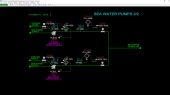
Sea Water System 1/2
Debris Filter, STR-103
Sea water from Sea Water Supply Pumps P-201I/J passes through the Debris Filter, STR-103 to remove any entrained debris that might enter the unit along with the sea water.
The Debris Filter has an auto-drain system that flushes accumulated debris to the sea water discharge line through MOV-104. MOV-100 and MOV-101 isolate the Debris Filter for servicing. In this case, Sea Water Supply Pumps P-201K and P-201L supply water to the unit by opening MOV-102 which is normally closed.
Sea water from STR-103 is used in three ways:
- As coolant for the Evaporator, HX-101. After the Evaporator, a portion of this sea water is fed to the Evaporator to produce distilled water.
- As coolant for the Vent Condenser, HX-105 which is in the Vacuum System. HX-105 cools and condenses vapor from the Deaerator, DA-101 before being sent to the Vacuum System ejectors.
- As coolant for the Cooling Water Coolers, HX-601I/J/K/L in the Service Cooling Water System.
- Sea water from these three systems are combined and discharged to the sea.
Vent Condenser, HX-105
The Vent Condenser HX-105 cools vent gas from the Deaerator to condense out some of the water vapor from the non-condensables released from feed sea water which are sent to the Vacuum System.
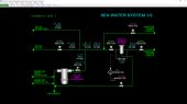
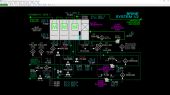
Sea Water System 2/2
Evaporator, HX-101
The Evaporator is a 24-cell multi-stage flash (MSF) evaporation unit with brine flowing through the bottom of each cell from Stage 1 to Stage 24. Each stage has a different pressure which is the equilibrium vapor pressure of the distillate produced in each cell which is based on the temperature of the distillate which, in turn, depends on the temperature of the coolant used in the condenser tubes at the top of the cells. Makeup sea water is used as coolant for the condensers in Stages 24, 23 and 22. Because feed sea water is the coldest coolant, the pressures of these stages are very low.
The normal flow of sea water through Stages 24 through 22 is 63.2 MGD and heats up to 98.5 DEG F in the condensers of these stages. After leaving the condenser of Stage 22, a portion of the warmed sea water is taken as feed to the Deaerator, DA-101. The normal flow rate of sea water to the Deaerator is 21.6 MGD.
The flow rate of sea water to discharge is normally 41.6 MGD.
A set of vapor lines from the top of each of the 24 cells to the Vacuum System ensures any dissolved gases that are released from the sea water feed do not accumulate in the cells, thereby causing the pressure to increase in the cells. These lines are combined and routed to the Vent Gas Condenser HX-103.
Sea Water Makeup Strainers, STR-101A/B
Sea water destined for the Deaerator, DA-101 is first filtered in the Sea Water Makeup Strainers, STR-101A/B to remove any particles and debris that are not removed by the Debris Filter, STR-103. If not removed, these particles will accumulate and foul the channels within the Evaporator, HX-101 over time. Normally, the “A” filter is in service, and the “B” filter is on standby.
Deaerator, DA-101
Warm sea water from the Sea Water Makeup Strainers,STR-101A/B is sent to the Deaerator, DA-101 to remove entrained and dissolved gases under vacuum conditions. Vent gas is routed to Vent Condenser, HX-105 to be cooled before being sent to the ejectors in the Vacuum System.
Sea Water Recirculation Pump, P-105
The Sea Water Recirculation Pump, P-105 is a motor-driven centrifugal pump used during wintertime conditions to keep the temperature of the sea water to the condenser of Stage 24 at or near its design value. Normally, the pump is not in operation because the sea water temperature is warm. The maximum capacity of P-105 is around 34 MGD. In case of low pump flow, a solenoid-operated valve, FV-141 recirculates sea water back to the pump suction to protect against dead-heading the pump.
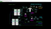
Brine System
Brine Recirculation Pump, P-101
Brine from Stage 24 is recirculated by the Brine Recirculation Pump, P-101 to the condenser of Stage 21. P-101 is a motor-driven centrifugal pump and is protected from dead-heading by opening solenoid-operated valve FV-243 to return some brine back to stage 24 in case of low flow in the pump line. The normal flow rate of recirculated brine is 77.7 MGD. Recirculated brine recovers the heat of condensation in the condensers of Stages 21 through Stage 1.
If there is a high level of brine in Stage 24, MOV-263 automatically opens to the brine blowdown line to help remove brine from the Evaporator.
Brine Blowdown Pump, P-104
Net brine produced from Stage 24 is pumped to the sea discharge line by the Brine Blowdown Pump, P-104 which is a motor-driven centrifugal pump. P-104 is protected from dead-heading by opening solenoid-operated valve FV-262 to return some brine back to stage 24 in case of low flow in the pump line. The normal flow rate of brine to the discharge line at battery limits is 12.71 MGD.
Sample Extraction Pump, P-107
A small flow of deaerated sea water from the base of Deaerator, DA-101 is pumped through a sampling loop back to the Deaerator by the Sample Extraction Pump, P-107. The air concentration of deaerated sea water is analyzed by this system and is normally 99 PPB (parts per billion).
Main Brine Heater, HX-102
Warm brine from the condenser of Stage 1 is heated by low pressure (LP) steam in the Main Brine Heater, HX-102. This temperature is commonly called the brine top temperature. The normal temperature is 219.2 DEG F. The normal flow of LP steam to HX-102 is 293 KLB/H.
Heater Drain Pump, P-103
Heater Drain Pump, P-103 is part of the Condensate System that is described later in this section.
Ball Strainer, STR-102
Prior to entering Stage 1 of the Evaporator, HX-101 the brine from the Main Brine Heater, HX-102 passes through Ball Strainer, STR-102 which is part of the Ball Cleaning System. STR-102 strains out cleaning balls that are occasionally circulated into the brine flowing through the condenser tubes of Stages 21 through Stage 1 and the tubes of Main Brine Heater, HX-102.
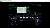
Distillate System
Distillate Pump, P-102
Distillate Pump, P-102 is a motor-driven centrifugal pump that pumps distillate collected in the well after Stage 24 through the vacuum system condensers, HX-301, HX-103 and HX-104, and on to the distillate distribution header where it can be routed to three destinations, depending on operations needs outside the MSF unit. Distillate can also be dumped to a discharge line if the conductivity is too high. High conductivity indicates an excessive amount of sea water has carried over to the distillate pans in the Evaporator making it unsuitable for drinking water standards.
A minimum flow line from the outlet of the three condensers recirculates distillate through FCV-442 back to the pan of Stage 22 during times of low distillate production. This has two benefits
- it prevents the pump from being dead headed
- it ensures enough flow through the three condensers to provide cooling capability for the condensers.
During startup when there is not yet distillate production, the heat picked up from the three condensers will be exhausted to sea water flowing through the condensers of Stages 22 through 24.
MOV-451 provides distillate to Stage 22 to inventory distillate in the system during startup. This is essential for commissioning the Vacuum System because the three condensers of the vacuum system need to have distillate flow in order for the Vacuum System to operate.
The normal flow of distillate through P-102 is 8.75 MGD.
Vacuum System Condensers, HX-301, HX-103 & HX-104 As mentioned above all the distillate from the Distillate Pump P-102 is routed through three heat exchangers in the Vacuum System:
- Vent Gas Condenser, HX-301 cools gases collected from Stages 1 through 24 prior to entering the ejectors of the Vacuum System.
- Primary Condenser, HX-103 condenses steam from the 1ST Stage Ejector EJ-101 of the Vacuum System
- Secondary Condenser, HX-104 which condenses steam from the 2ND Stage Ejector, EJ-102 of the Vacuum System
Distillate Header
Net distillate produced by the Evaporator is routed to a header for distribution or it can be routed to a dump line for disposal in case the conductivity of the distillate is too high. Solenoid-operated valves CV-441A and CV-441B are interlocked and control the routing to the distillate header or the dump line.
Three MOV’s determine routing of distillate out of the header:
- MOV-449A routs distillate from the MSF unit to the site’s “A” distillate header
- MOV-449B routs distillate from the MSF unit to the site’s “B” distillate header
- MOV-450 routs distillate from the MSF unit to the site’s boiler makeup water treating facilities
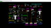
Vacuum System
Vent Condenser, HX-105
Gases stripped from sea water in the Deaerator are sent to the Vent Condenser, HX-105 through hand valve HV-525. Sea water from the outlet of Debris Filter, STR-103 is used as coolant on the tube side of HX-105. Any condensed water is assumed to be automatically removed from the base of the shell side of HX-105.
Vent Gas Condenser, HX-301
Gases vented from the vapor space of Stages 1 through 24 of the Evaporator, HX-101 are collected and sent to the Vent Gas Condenser, HX-301 through hand valve HV-501. Distillate from Distillate Pump, P-102 is used as coolant for HX-301. Any condensed water is assumed to be automatically removed from the base of the shell side of HX-301.
Startup Ejector, EJ-103
The Startup Ejector, EJ-103 provides vacuum for the Evaporator, HX-101 and the Deaerator, DA-101 during startup of the unit. It is a high-capacity ejector and its exhaust vents to atmosphere via a silencer. Motor controlled valve MOV-530 routes non-condensable gases from Vent Condenser, HX-105 and Vent Gas Condenser, HX-301 to EJ-103.
Medium pressure (MP) steam is supplied to EJ-103 from a steam distribution header through MOV-618. While EJ-103 is a high-capacity ejector, it cannot attain very deep vacuum at the outlet of HX-105 because it is a single-stage ejector. EJ-103 is used at startup to remove much of the air from the Evaporator prior to starting the two-stage ejector system. The two-stage ejector system, EJ-101 and EJ-102 have lower vapor drawing capacity than EJ-103 but can attain deeper vacuum owing to its two-stage configuration.
1ST Stage Ejector, EJ-101
The 1ST Stage Ejector, EJ-103 is used during normal operations to provide vacuum for the Deaerator, DA-101 via the Vent Condenser, HX-105 and the 24 cells of the Evaporator, HX-101 via the Vent Gas Condenser, HX-301.
MOV-531 routes gases from the outlets of HX-105 and HX-301 to EJ-101’s vacuum port. MOV-614 provides MP steam from the MP steam header to both EJ-101 and 2ND Stage Ejector, EJ-102. The compressed gas and steam leaving EJ-101 is routed to the Primary Condenser, HX-103 to cool the stream and condense most of the steam.
Primary Condenser, HX-103
The Primary Condenser, HX-103 condenses exhaust steam from the 1ST Stage Ejector, EJ-101 using distillate from Vent Gas Condenser, HX-301. Condensate is assumed be automatically removed from the base of the shell side of HX-103.
HX-103 also cools any air removed from Main Brine Heater, HX-102 via MOV-533 during startup or in case of a vacuum leak in HX-102. The cooled gases leaving HX-103 are routed to the 2ND Stage Ejector EJ-102 via MOV-532.
2ND Stage Ejector, EJ-102
The 2ND Stage Ejector, EJ-102 compresses net gas from the Primary Condenser, HX-103 using MP steam provided from the MP steam header via MOV-614. The split of steam flow from MOV-614 to EJ-101 and EJ-102 is normally 50%/50%. The compressed gas and steam leaving EJ-102 is routed to the Secondary Condenser, HX-104 to cool the stream and condense most of the steam.
Secondary Condenser, HX-104
The Secondary Condenser, HX-104 condenses exhaust steam from the 2ND Stage Ejector, EJ-102 using distillate from Primary Condenser, HX-103. Condensate is assumed be automatically removed from the base of the shell side of HX-104. The cooled gases leaving HX-104 are slightly above atmospheric pressure and are routed to atmosphere via hand valve HV-532.
Main Brine Heater, HX-102
During startup the Main Brine Heater HX-102 is purged of air by opening MOV-533 to pull vacuum on the shell side of HX-102.
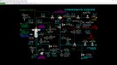
Condensate System
Desuperheater, X-101
The Desuperheater X-101 cools hot low pressure (LP) steam from battery limits before it enters the Brine Heater, HX-102. The cooled steam prevents fouling due to high tube temperatures on the brine side of the tubes of HX-102. The Desuperheater uses condensate from Heater Drain Pump, P-103 to quench (attemperate, desuperheat) the hot LP steam flowing through MOV-600 and control valve PCV-602.
MP steam flowing through FV-730 distributes condensate to the injectors of X-101 so it mixes evenly with the hot LP steam entering the Desuperheater. The condensate quickly vaporizes in X-101, causing the temperature of the mixture to decrease yet still remain all vapor. The desuperheated steam from X-101 is routed to the shell side of the Main Brine Heater HX-102 through control valve FCV-603.
Main Brine Heater, HX-102
The Main Brine Heater, HX-102 heats up circulating brine from the condenser of Stage 1 of Evaporator, HX-101. Normally, the brine enters HX-102 at 207.1 DEG F and leaves at 219.2 DEG F. The desuperheated steam enters the shell side of HX-102 at 237.0 DEG F. All of the steam condenses in HX-102 and collects in the bottom of the shell. A connection for inventorying HX-102 with distillate at startup is provided through hand valve HV-700. This is important for establishing operation of the Condensate System because it must be in service before LP steam can be brought in to the Main Brine Heater HX-102.
Heater Drain Pump, P-103
Heater Drain Pump, P-103 is a motor-driven centrifugal pump that pumps steam condensate from HX-102 to the condensate return header and to the Desuperheater, X-101. P-103 is protected from dead-heading by opening solenoid-operated valve FV-721 to return some condensate back to HX-102 in case of low flow. The normal flow rate of condensate to the condensate return line is 614 GPM.
During startup, when distillate is used to establish the Condensate System, it is necessary to divert condensate to the condensate dump line because its conductivity (i.e., its dissolved mineral content) is too high to return to the condensate return line for reuse as boiler feed water. Solenoid-operated valves CV-720A and CV-720B are interlocked and control the routing to the condensate return header or the condensate dump line. MOV-722 ensures no flow to the condensate return line in case there is a problem with the solenoid operated valves.
Condensate System Interlocks
There are many protective interlocks for the Condensate System. These are discussed in the Instrumentation Section. These interlocks are designed to protect the Brine Heater from being subjected to damage from high temperatures during operation.
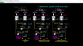
Chemical Injection System
Anti-Scale Tanks, TK-101A/B
Anti-scale Tanks, TK-101A/B hold anti-scale solution, which is injected to the Deaerator, DA-101 and circulated throughout the Evaporator, HX-101 by the Brine Recirculation Pump, P-101.
The anti-scale solution prevents buildup of minerals on the surfaces of the piping, tubes, cells and channels of the Evaporator. Both tanks are outfitted with agitators to keep the solution concentration uniform. The tanks normally hold about 2 hours of solution. The “A” tank is normally in service. A fill function is provided on the simulator so that the tanks can be refilled (this is normally done manually at the tank by adding solution from drums). The anti-scale solution is pumped to the Deaerator by Anti-scale Injection Pumps, P-108A/B.
Anti-scale Injection Pumps, P-108A/B
Anti-scale Injection Pumps, P-108A/B are small, motor-driven chemical dosing pumps with adjustable stroke length to control the rate of dosing to the Deaerator. Normally only P-108A is in operation with P-108B on standby. The normal dosing rate of anti-scale solution is 609 LB/H.
Note: effects on the Evaporator as a result of adding or not adding this solution are not simulated since these effects are manifested over long periods of time.
Sulfite Tanks, TK-102A/B
Sulfite Tanks, TK-102A/B hold sodium sulfite solution which is injected to the suction of Brine Recirculation Pump, P-101 and circulated throughout the Evaporator, HX-101. This solution scavenges oxygen from the circulating brine to prevent long-term corrosion of Evaporator HX-101 equipment and piping.
Both tanks are outfitted with agitators to keep the solution concentration uniform. The tanks hold about 2 hours of solution. The “A” tank is normally in service. A fill function is provided on the simulator so that the tanks can be refilled (this is normally done manually at the tank by adding solution from drums). The sulfite solution is pumped to the Brine Recirculation Pump, P-101 by Sulfite Injection Pumps, P-109A/B.
Sulfite Injection Pumps, P-109A/B
Sulfite Injection Pumps, P-109A/B are small, motor-driven chemical dosing pumps with adjustable stroke length to control the rate of dosing of sulfite solution to the Brine Recirculation Pump, P-101. Normally only P-109A is in operation with P-109B on standby. The normal dosing rate of anti-scale solution is 300 LB/H.
Note: effects on the Evaporator as a result of adding or not adding this solution are not simulated since these effects are manifested over long periods of time.
Anti-foam Tanks, TK-103A/B
Anti-foam Tanks, TK-103A/B hold anti-foam solution which is injected to the sea water makeup line to the Deaerator DA-101 and circulated throughout the Evaporator HX-101. This solution breaks up any foam that may form on the top of brine levels throughout Evaporator HX-101.
Both tanks are outfitted with agitators to keep the solution concentration. The tanks hold about 2 hours of solution. The “A” tank is normally in service. A fill function is provided on the simulator so that the tanks can be refilled (this is normally done manually at the tank by adding solution from drums). The anti-foam solution is pumped to the Deaerator sea water feed line by Anti-foam Injection Pumps, P-112A/B.
Anti-foam Injection Pumps, P-112A/B
Anti-foam Injection Pumps, P-112A/B are small, motor-driven chemical dosing pumps with adjustable stroke length to control the rate of dosing of anti-foam solution to the sea water feed line to the Deaerator DA-101. Normally only P-112A is in operation with P-112B on standby. The normal dosing rate of anti-scale solution is 90 LB/H.
Note: effects on the Evaporator as a result of adding or not adding this solution are not simulated since these effects are manifested over long periods of time.
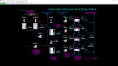
Service Cooling Water System
The Service Cooling Water System provides circulating cooling water for protection of the Sea Water Pumps, P-201I/J/K/L and other cooling equipment outside the unit.
Corrosion Inhibitor Tanks, TK-611E/F
Corrosion Inhibitor Tanks, TK-611E/F hold corrosion inhibitor solution, which is injected to Cooling Water Expansion Tanks, TK-601E/F on an as-needed basis. This solution inhibits corrosion of Service Cooling Water System piping and equipment.
Both tanks are outfitted with agitators to keep the solution concentration uniform in the tanks. The tanks normally hold about 2 hours of solution when corrosion inhibitor is being added. Normally, neither is in service. A fill function is provided on the simulator so that the tanks can be refilled (this is normally done manually at the tank by adding solution from drums). The corrosion inhibitor solution is pumped to the Expansion Tanks by Corrosion Inhibitor Injection Pumps, P-611E/F.
Corrosion Inhibitor Injection Pumps, P-611E/F
Corrosion Inhibitor Injection Pumps, P-611E/F are small, motor-driven chemical dosing pumps. These pumps deliver a fixed dosing flow of corrosion inhibitor solution to the Expansion Tanks TK-601E/F. Normally neither pump is in operation.
Note: effects on the Evaporator as a result of adding or not adding this solution are not simulated since these effects are manifested over long periods of time.
Expansion Tanks, TK-601E/F
Warm cooling water collects from users via the Cooling Water Return Header. Two elevated Expansion Tanks, TK-601E/F connect to the header for expansion of the water in the system due to changes with temperature. Water is denser at lower temperatures, so for a fixed mass of water in the system, the volume is lower, and the expansion tanks will transfer some of its water to the Return Header by gravity. Conversely, when the cooling water becomes hotter it occupies more volume and water from the Return Header is pushed up into the tanks as the water expands.
In case of leaks or maintenance purges of cooling water from the system, distillate from the site-wide distillate header is used to fill the Expansion Tanks to their normal levels. Corrosion inhibitor should be added to the Expansion Tanks, if this is needed.
Cooling Water Pumps, P-601I/J/K/L
Four motor-driven, centrifugal Cooling Water Pumps, P-601I/J/K/L pump cooling water from the Return Header through the Cooling Water Coolers, HX-601I/J/K/L and into the two Cooling Water Supply Headers (A & B). Normally, only pumps P-601I/J are in operation. The flow of each pump is normally 2,625 GPM.
Cooling Water Coolers HX-601I/J/K/L
The returned, warm cooling water is cooled with sea water taken downstream of Debris Filter, STR-103 by Cooling Water Coolers, HX-601I/J/K/L. The warmed sea water is returned to the sea via a discharge line at the battery limits. At design, the cooling water supply temperature is 85.9 DEG F. The cooling water return temperature is 129.5 DEG F.
Cooling Water Supply and Return Headers
The two cooling water supply headers (denoted as “A” and “B”) supply cooled
water from the Cooling Water Coolers to various equipment outside the unit and to Sea Water Pumps, P-201I/J/K/l/L for lubrication and cooling of the pump bearings.
Cooling water from the “A” header supplies the Sea Water Pumps P-201I/K while the “B” header supplies Sea Water Pumps P-201J/L. Cooling water returns to the Cooling Water Pumps by a common line to the Cooling Water Return Header. Cooling water is also supplied to equipment external to unit (not shown on Schematic #13) and returned to the Cooling Water Return Header.
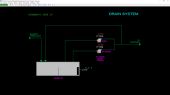
Drain System
Sump Pit
The drain system consists of a Sump Pit that collects any runoff from the MSF unit such as rain water or maintenance purges, etc. Runoff water will collect in the Sump Pit until it is pumped out using the Sump Pumps, P-110A/B.
Sump Pumps, P-110A/B
Sump Pumps, P-110A/B are motor-driven centrifugal pumps which pump water from the Sump Pit to disposal facilities at the battery limit. These pumps have sufficient capacity to empty the Sump Pit in about 4 minutes if it is completely full.
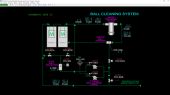
Ball Cleaning System
The Ball Cleaning System circulates small rubber balls through the tubes of condensers of Stages 21 through Stage 1 of Evaporator HX-101 and through the tubes of Brine Heater, HX-102. These balls are slightly smaller than the tube diameters so they can pass through the tubes. The balls scrape against the tube walls to dislodge any scale (hardened salts) on the tube walls.
This system is used periodically to maximize heat transfer rates over time. The system is normally not running, and its use or lack of use has no effect on the performance of the Evaporator or the Brine Heater in the simulator since these effects are manifested over long periods of time.
Ball Collector, X-102
The Ball Collector, X-102 is vessel which contains a flap to retain the balls within X-102. This flap can be moved to the release position to circulate balls through the piping and tubes of the Evaporator, HX-101 and the Main Brine Heater, HX-102. Hand valve POV-837A will direct the balls to be released into the condenser tubes of Stages 21 through 1 and then through the Main Brine Heater. Alternatively, opening just POV-837B will direct the balls to only the Main Brine Heater. When the flap is in the hold position, any balls returned to X-102 will be retained within X-102.
Ball Strainer, STR-102
Ball Strainer STR-102 collects the balls returning in the circulating brine from HX-102 using an angled plate with holes having diameters smaller than the diameters of the cleaning balls. The balls then deflect from the angled plate into a collection well below the strainer. The balls can then be moved back to the ball collector via hand valve POV-832A.
Ball Cleaning Pumps, P-106A/B
Ball Cleaning Pumps P-106A/B are motor-driven specialty pumps that allow the cleaning balls to pass through them. These pumps are used to either route balls from the Ball Strainer to the Ball Collector or to push the cleaning balls out of the Ball Collector into the circulating brine line of the Evaporator HX-101. When pushing balls out of the Ball Collector, hand valve POV-832B is opened to route circulating brine through the Ball Cleaning Pumps and into the Ball Collector.
The simulator allows practicing the ball cleaning procedure and provides indications of the ball inventories in the Ball Collector X-102, in the brine recirculation piping and in the Ball Strainer STR-102. This is described in the Instrumentation section.
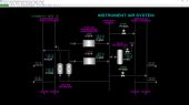
Instrument Air System
The Instrument Air System provides instrument air to the unit control valves. The system generally does not affect the operation of the MSF except in case of low instrument air pressure where control valves will move to their fail position.
Packaged Air Compressors, C-631A/B
These packaged air compressor systems are simulated as a “black box”. When a compressor is running, it will deliver compressed air to the Air Supply Header at a constant flow rate. Also, a maximum temperature in the system is calculated based on whether the compressor is running and based on the pressure of the Air Supply Header. C-631A is normally in operation with C-631B on standby.
Air Supply Header
The Air Supply Header distributes compressed air to the two Service Air Supply Headers (“A” and “B”) via solenoid-operated valves PV-922A and PV-922B. Service air is used for general use within the plant. Normally, 25% of the air flow from one Air Compressor is distributed to the “A” Service Air Supply Header and another 25% to the “B” Service Air Supply Header. The Air Supply header is also connected to the Air Receiver, TK-631 and supplies air to the Instrument Air Headers via Air Dryers V-631A/B. Normally 50% of the air flow from one Air Compressor is distributed to the Instrument Air Headers.
Air Receiver, TK-631
The Air Receiver, TK-631 serves as a large air reservoir for the Instrument Air System so that in case of a failure of one of the Packaged Air Compressors the air pressure will not drop quickly. This allows time for the operator to start the standby Air Compressor without any effect on unit control valves.
TK-631 is outfitted with a self-regulating pressure control valve PCV-914 which will regulate the pressure of TK-631 to be around 120 PSIG. This valve vents excess air to atmosphere.
Air Dryers, V-631A/B
The Air Dryers, V-631A/B use a desiccant (drying beads) to remove moisture from the air flowing to the Instrument Air Headers. The Air Dryers are always assumed to be in service. The pressure drop across the Air Dryers is normally 4.0 PSI.
Instrument Air Supply Headers
The two Instrument Air Supply Headers (“A” and “B”) supply air to the control valves in the MSF unit. Normally, 25% of the air of one Air Compressor is distributed to the “A” Instrument Air Supply Header and another 25% to the “B” Instrument Air Supply Header. The pressures of these headers are normally around 114 PSIG.
The pressure will only impact the operation of the control valves should the pressure drop below 14.7 PSIG.
Instrumentation
Overview
This section describes the controls and instruments of the MSF unit
Sea Water Pumps
Sea Water Supply Pumps, P-201I/J/K/L
The Sea Water Pumps P-201I/J/K/L are outfitted with the following instruments:
- Switches FV-974I/J/K/L open/close cooling water to respective pump bearings
- Switches P-201I/J/K/L start/stop the respect pump’s motor
- Indicators TI-152I/J/K/L indicate and alarm pump’s bearing temperature
- Indicators PI-160I/J/K/L to indicate and alarm pump discharge pressure
- Switch MOV-161I/J/K/L open/close the respective pump’s discharge motor operated valve (MOV)
Each pump has an interlock circuit that automatically closes the respective discharge MOV on low pressure. The set pressure for the interlock is 20 PSIG. The discharge MOV can be closed at any time using its respective switch, although it is not recommended to do this while the pump is running.
The discharge MOV can only be opened once the pump’s discharge pressure is above 20 PSIG. The discharge MOV should be opened shortly after starting the pump so as not to dead-head the pump too long and cause mechanical damage to the seals, etc.
Normally P-201I/J are in operation and P-201K/L are on standby.
Sea Water System 1/2
Debris Filter, STR-103
Switch MOV-100 opens and closes motor operated valve MOV-100 at the inlet to Debris Filter, STR-103. MOV-101 opens and closes motor operated valve MOV-101 at the outlet of STR-103. Normally, these two valves are open.
PI-102 indicates the pressure at the inlet of the Debris Filter. PI-101 indicates the pressure of the sea water at the outlet of the Debris Filter downstream of MOV-101. TI-101 indicates the temperature of the sea water at this point.
PDI-104 indicates the pressure drop across STR-103. PDHH-104 is a switch that indicates and alarms high-high pressure across STR-103 causing interlock I-29 to automatically place switch MOV-104 in the OPEN position and open the valve.
This causes STR-103 to purge any accumulated debris to the sea water discharge line. After the pressure drop has been restored to normal values, MOV-104 must be closed manually using switch MOV-104. MOV-104 can be opened at any time. It can only be closed as long as there is not high-high pressure drop across STR-103.
MOV-102 allows flow from Sea Water Pumps P-201K/L to be used in the MSF unit when the Debris Filter, STR-103 needs to be taken out of service. Switch MOV-102 is used to open and close MOV-102. Normally MOV-102 is closed and sea water is supplied by Sea Water Pumps, P-201I/J through the Debris Filter.
MOV-105 is opened and closed by switch MOV-105. MOV-105 supplies water to the Evaporator HX-101. Normally MOV-105 is open. It is closed when the unit is shut down to prevent sea water from entering the Evaporator if a Sea Water pump is inadvertently started.
The flow of sea water to Evaporator, HX-101 is indicated on FI-101. FI-102 indicates the flow of sea water to Cooling Water Coolers, HX-601I/J/K/L.
Vent Condenser, HX-105
FI-103 indicates the flow of sea water to Vent Condenser HX-105. The flow of sea water to HX-105 is manually controlled by adjusting the output of hand controller HIC-103 which adjusts the position of control valve HCV-103.
Sea Water System 2/2
Evaporator, HX-101
FI-106 indicates the flow of cooling sea water to the condenser tubes of Stage 24 of Evaporator HX-101. PI-106 indicates the pressure of sea water at that point. TIC-106 controls the temperature of the sea water by adjusting the position of TCV-106 to regulate the flow of warm recycled sea water from Stage 22. Normally TIC-106 is in manual mode with an output of 0%. TIC-106 is only used when the sea water temperature becomes cooler during the wintertime.
Hand controllers HIC-108A/B adjust the position of discharge control valves HCV-108A/B, respectively. The sea water discharge flow rate is indicated on FI-108.
Note that when TIC-106 is commissioned, this requires Sea Water Recirculation Pump, P-105 to be started (see below). Also, the flow of sea water to discharge should be reduced using HIC-108A/B to avoid over-cooling Stages 22 through 24. This will allow TIC-106 to maintain control of the sea water temperature to the condenser of Stage 24.
CI-323 indicates the conductivity of the brine in Stage 23 of the Evaporator.
Sea Water Makeup Strainers, STR-101A/B
Switch STR-101 selects which of the Sea Water Makeup Strainers, STR-101A/B is in service. PDI-101A indicates the pressure drop across STR-101A while PDI-101B indicates the pressure drop across STR-101B.
PI-111 indicates the pressure at the outlet of STR-101A/B. FIC-112 controls the flow of sea water to the Deaerator DA-101 by adjusting control valve FCV-112.
Sea Water Recirculation Pump, P-105
Switch P-105 is used to start and stop the motor of Sea Water Recirculation Pump, P-105. PI-140 indicates the discharge pressure of P-105 while FI-141 indicates the flow of recirculated sea water through TCV-106.
Switch FV-141 indicates the state of solenoid-operated valve FV-141. FV-141 is a minimum flow valve that is automatically opened by interlock I-01 when FI-141 indicates below 10.8 MGD and P-105’s motor is running. FV-141 is an indicate-only switch.
TI-132 indicates the P-105 motor temperature. TAHH-132 indicates and alarms if TI-132 exceeds the high-high motor temperature trip setpoint of 185 DEG F. Interlock I-26 will stop P-105 by locking switch P-105 in the STOP position. P-105 can be restarted once TAHH-132 is not in the HI-HI state.
Brine System 1/2
Evaporator, HX-101 (Heat Rejection Section)
Stage 24
TI-524 indicates the temperature in the vapor space of Stage 24 by the condenser tubes. PI-524 indicates the pressure at the top of Stage 24. TI-324 indicates the temperature of brine in Stage 24.
TI-424 indicates the temperature of distillate in the distillate collection pan of Stage 24. LIC-324 controls the level of brine in Stage 24 by adjusting the opening of control valve LCV-324 on the brine blowdown line to discharge.
LAH-324 is a switch that indicates if LIC-324 level is high (setpoint = 80%) and is used by interlock I-09 to open MOV-263 on the brine recirculation line (see Brine Recirculation Pump below). Opening MOV-263 will divert some of the recirculating brine through LCV-324 in order to increase the flow of brine to discharge.
LALL-324 is a switch that indicates if LIC-324 level is low-low (setpoint = 5%) and is used by interlock I-06 to stop Brine Recirculation Pump P-101 so it does not cavitate. LLLL-324 is a switch that indicates if LIC-324 level is low-low-low (setpoint = 2%) and is used by interlock I-08 to stop Brine Blowdown Pump P-104 so it does not cavitate.
Stage 23
CI-323 indicates the conductivity of brine in Stage 23.
Stage 22
TI-522 indicates the temperature in the vapor space of Stage 22 by the condenser tubes. TI-322 indicates the temperature of brine in Stage 22.
Brine Recirculation Pump, P-101
Switch P-101 is used to start and stop the motor of Brine Recirculation Pump P-101. As mentioned above, interlock I-06 will lock switch P-101 in the STOP state when LALL-324 is in the LO-LO state.
PI-241 indicates the discharge pressure of P-101 and TI-241 indicates the discharge temperature. CI-241 indicates the conductivity of the recirculating brine.
Switch FV-243 indicates the state of solenoid-operated valve FV-243. FV-243 is a minimum flow valve that is automatically opened by interlock I-02 when recirculating brine flow indicator FI-243 indicates below 48.6 MGD7,653 T/H and P-101’s motor is running. FV-243 is an indicate-only switch. FAL-243 is a switch that indicates the state of FI-243 being in the PV low alarm condition.
TI-232 indicates the temperature of P-101’s motor. TAHH-232 indicates and alarms if TI-232 exceeds the high-high motor temperature trip setpoint of 185 DEG F85 DEG C. Interlock I-26 will stop P-101 by locking switch P-101 in the STOP position. P-101 can be restarted once TAHH-232 is not in the HI-HI state.
Hand controllers HIC-242A/B adjust the position of brine recirculation control valves HCV-242A/B, respectively. The flow rate of recirculating brine to the condenser tubes of Stage 21 is indicated on FI-243. As mentioned above, FI-234 is used to open and close FV-243 to protect P-101 from dead-heading. Additionally, if FI-324 is very low (less than 21.6 MGD3,400 T/D) interlock I-03 will stop LP steam to the Condensate System by closing MOV-600 (see the Condensate System instrumentation details later in this section). The low-low flow will be indicated on switch FALL-243 and an alarm will sound.
Switch MOV-263 opens and closes brine crossover valve MOV-263 to divert some of the recirculating brine flow to the brine blowdown line just upstream of brine level control valve LCV-324. MOV-263 can be opened at any time, but Brine Blowdown Pump P-104 should be stopped when it is opened to avoid dead-heading P-104 since P-104 is a lower head pump than Brine Recycle Pump P-101. As mentioned above, interlock I-09 will automatically lock switch MOV-263 in the OPEN position while LAH-324 indicates HIGH. MOV-263 must be closed manually after LAH-324 indicates OK.
Brine Blowdown Pump, P-104
Switch P-104 is used to start and stop the motor of Brine Blowdown Pump P-104. As mentioned above, interlock I-08 will lock switch P-104 in the STOP state when LLLL-324 is in the LLL state.
PI-261 indicates the discharge pressure of P-104 and TI-261 indicates the discharge temperature. CI-261 indicates the conductivity of the blowdown brine.
Switch FV-262 indicates the state of solenoid-operated valve FV-262. FV-262 is a minimum flow valve that is automatically opened by interlock I-04 when blowdown brine flow indicator FI-262 indicates below 5.4 MGD850 T/H and P-104’s motor is running. FV-262 is an indicate-only switch. FAL-262 is a switch that indicates the state of FI-262 being in the PV low alarm condition.
TI-252 indicates the temperature of P-104’s motor. TAHH-252 indicates and alarms if TI-252 exceeds the high-high motor temperature trip setpoint of 185 DEG F85 DEG C. Interlock I-26 will stop P-104 by locking switch P-104 in the STOP position. P-104 can be restarted once TAHH-252 is not in the HI-HI state.
Sample Extraction Pump, P-107
Switch P-107 is used to start and stop the motor of Sample Extraction Pump, P-107. AI-117 indicates the concentration of dissolved oxygen in the Deaerator sea water.
Evaporator, HX-101 (Heat Recovery Section)
Stage 1
PI-501 indicates the pressure at the top of Stage 1 of the Evaporator. TI-501 indicates the temperature in the vapor space by the condenser tubes. LI-301 indicates the level of brine in Stage 1. TI-301 indicates the temperature of brine.
TI-200 indicates the temperature of recirculating brine leaving the condenser tubes of stage 1. PI-200 indicates the pressure of the recirculating brine leaving the condenser tubes of Stage 1.
Stage 21
TI-521 indicates the temperature in the vapor space of Stage 21 by the condenser tubes. TI-321 indicates the temperature of brine in Stage 21.
TI-244 indicates the temperature of recirculating brine entering the condenser tubes of stage 21. PI-244 indicates the pressure of the recirculating brine entering the condenser tubes of Stage 21. FI-243 indicates the flow of recirculating brine to the condenser tubes of Stage 21.
Main Brine Heater, HX-102
The outlet temperature of the recirculating brine from HX-102 is controlled by TIC-300 which adjusts the setpoint of LP steam flow controller FIC-603. The pressure of the recirculating brine at the outlet of HX-102 is indicated on PI-300.
The pressure of the steam to HX-102 is indicated on PI-606. The temperature of the steam is controlled by TIC-607 which adjusts the flow of condensate to the Desuperheater X-101. The temperature of the vapor space in the shell side of HX-102 is indicated on TI-608. The pressure of the steam on the shell side of HX-102 is indicated on PI-608. The level of condensate in the base of the shell side of HX-102 is controlled by LIC-700 which adjusts the flow of condensate to the condensate return header at battery limits.
Heater Drain Pump, P-103
Switch P-103 is used to start and stop the motor of Heater Drain Pump P-103. CIC-720 indicates the conductivity of the condensate. FI-720 indicates the flow rate of condensate from P-103. PI-720 indicates the discharge pressure of P-103.
Ball Strainer STR-102
Prior to entering Stage 1 of the Evaporator, the brine from the Main Brine Heater HX-102 passes through Ball Strainer STR-102 which is part of the Ball Cleaning System. STR-102 strains out cleaning balls that are occasionally circulated into the brine flowing through the condenser tubes of Stages 21 through Stage 1 and the tubes of HX-102.
Distillate System
Evaporator, HX-102 (Heat Rejection Section)
Stage 24
TI-524 indicates the temperature in the vapor space of Stage 24 by the condenser tubes. PI-524 indicates the pressure at the top of Stage 24. TI-424 indicates the temperature of distillate in the distillate collection pan of Stage 24. TI-324 indicates the temperature of brine in Stage 24.
LIC-424 controls the level of distillate in the collection well attached to Stage 24 by adjusting the opening of control valve LCV-424 on the distillate line to the distillate headers/distillate dump line.
LALL-424 is a switch that indicates if LIC-424 level is low-low (setpoint = 5%) and is used by interlock I-12 to stop Distillate Pump P-102 so it does not cavitate.
Stage 22
TI-522 indicates the temperature in the vapor space of Stage 22 by the condenser tubes.
Distillate Pump, P-102
Switch P-102 is used to start and stop the motor of Distillate Pump P-102. As mentioned above, interlock I-12 will lock switch P-102 in the STOP state when LALL-424 is in the LO-LO state.
PI-441 indicates the discharge pressure and TI-441 indicates the discharge temperature of P-102.
CIC-441 indicates the conductivity of the distillate. CIC-441 is a switching controller that when placed in AUTO will switch the distillate diversion valves CV-441A and CV-441B in case of high distillate conductivity. If the conductivity is more than 12.0 μS/cm, CV-441B will be opened to send distillate to the distillate dump line at battery limits and CV-441A will be closed to block sending any distillate to the distillate header. Switches CV-441A and CV-441B indicate the state of these solenoid-operated valves. These switches do not operate the valves. Diversion of distillate can be done manually using CIC-441 when in MAN mode.
FIC-442 is a minimum flow controller that ensures high enough flow of distillate from P-102 through the three condensers of the Vacuum System, HX-301, HX-103 and HX-104. FIC-442 adjusts the position of control valve FCV-442 which returns some or all of the distillate leaving HX-104 back to the distillate collection pan of Stage 22. FIC-442 also protects the Distillate Pump from being dead-headed. Normally, FCV-442 is closed.
TI-432 indicates the temperature of P-102’s motor. TAHH-432 indicates and alarms if TI-432 exceeds the high-high motor temperature trip setpoint of 185 DEG F85 DEG C. Interlock I-26 will stop P-102 by locking switch P-102 in the STOP position. P-102 can be restarted once TAHH-432 is not in the HI-HI state.
TI-446 indicates the temperature of distillate leaving Secondary Condenser HX-104.
Switch MOV-451 opens and closes the startup distillate valve MOV-451, which is normally closed.
Distillate Header
FI-448 indicates the flow of distillate to the distillate header. Note that FI-448 is situated downstream of distillate diversion valve CV-441A so that if distillate is being diverted to dump, FI-448 will indicate a flow of zero.
Switches MOV-449A, MOV-449B and MOV-450 open and close their respective MOVs which route distillate to two distillate headers and to boiler makeup water at battery limits. Normally, only MOV-449A is open.
Vacuum System
Vent Gas Condenser, HX-301
Hand controller HIC-501 adjusts the opening of field valve HV-501 to regulate the flow of vent gases from the Stages 1 through 24 of Evaporator HX-101 to Vent Gas Condenser, HX-301. Normally this valve is 10% open to minimize excessive water vapor draw from the Evaporator. If an air pocket is suspected in any of the cells, the valve can be opened as needed to pull air from the cell using HIC-501.
The temperature of distillate to HX-301 is indicated on TI-441 and the flow of distillate is indicated on FIC-442 (see Distillate System previously in this section for details of FIC-442 operation). Switch FAL-442 will indicate LOW if the flow of FIC-442 is less than 3.24 MGD. FAL-442 is used by interlock I-10 which will isolate the 1ST and 2ND Stage Ejectors, EJ-101 and EJ-102 because there will be insufficient distillate flow to condense the steam from these ejectors in the downstream condensers, Primary Condenser HX-103 and Secondary Condenser HX-104.
Vent Condenser, HX-105
Hand controller HIC-525 adjusts the opening of field valve HV-525 which controls the flow of vent gases from the Deaerator DA-101 to Vent Condenser HX-105. Normally this valve is 100% open. Hand controller HIC-103 adjust the position of control valve HCV-103 which controls the flow of sea water to the tubes of HX-105. The flow of sea water is indicated on FI-103. The pressure at the outlet of HX-105 on the shell side is indicated on PI-530. This is the lowest vacuum pressure in the Vacuum System.
Hand controller HIC-102 adjusts the opening of vacuum breaker valve HV-102. This valve is normally closed. It is used at shutdown to break the vacuum in HX-105 and in the Deaerator and Stages 1 through 24 of Evaporator HX-101.
Cooled and condensed vent gas from HX-105 combine with cooled vent gas from HX-301 and are normally directed to the 1ST Stage Ejector EJ-101. During startup, when there is a lot of air to evacuate from the Evaporator HX-101, the combined gases are initially sent to the Startup Ejector EJ-103. After sufficient air evacuation of the Evaporator has been made, the 1ST and 2ND Stage Ejectors are placed in service and the Startup Ejector is stopped.
1ST Stage Ejector, EJ-101
Switch MOV-531 opens and closes MOV-531 to route combined gases from HX-105 and HX-301 to 1ST Stage Ejector EJ-101. Switch MOV-614 opens and closes MOV-614 to bring in MP steam to both EJ-101 and 2ND Stage Ejector EJ-102. The flow of steam through MOV-614 is indicated on FI-612. Switch FAL-612 will indicate LOW if the flow of FI-612 is less than 5.25 KLB/H2.38 T/H.
FAL-612 is used by interlock I-14 which will isolate the 1ST and 2ND Stage Ejectors, EJ-101 and EJ-102 because there will be insufficient steam to the ejectors. Note that at startup, FAL-612 must be bypassed in order to open MOV-614 and admit steam to the ejectors. Switch HS-612 is used to bypass FAL-612 by placing HS-612 in the BYPS position. After bypassing FAL-612, I-14 will reset HS-612 back to the ARMED position after 30 seconds, so opening MOV-614 during startup must be made immediately after FAL-612 is bypassed using HS-612 in order to avoid re-tripping I-14.
The switches for MOV-531 and MOV-614 are placed in the CLSD position by either interlock I-10 (see above, low distillate flow to HX-301) or I-14 which is described in the previous paragraph.
Primary Condenser HX-103
PI-531 indicates the pressure of gas leaving the shell side of Primary Condenser HX-103.
2ND Stage Ejector, EJ-102
Switch MOV-532 opens and closes MOV-532 to route cooled gas from Primary Condenser HX-103 to the 2ND Stage Ejector EJ-102. Switch MOV-614 opens and closes MOV-614 to admit steam to both EJ-101 and EJ-102, as described previously. The switch for MOV-532 is placed in the CLSD position by either interlock I-10 or I-14 which are described in the previous paragraphs.
Secondary Condenser, HX-104
PI-532 indicates the pressure of gas leaving the shell side of Secondary Condenser HX-104. Switch HV-532 opens and closes the field valve of the vent from the shell side of HX-104 to atmosphere.
Main Brine Heater, HX-102
Switch MOV-533 opens and closes MOV-533 to allow vacuum to be pulled on the shell (steam) side of Main Brine Heater HX-102 during startup to purge air from the heater. The switch for MOV-533 is placed in the CLSD position by either interlock I-10 or I-14 which are described in the previous paragraphs. PI-608 indicates the pressure on the shell (steam) side of HX-102.
Startup Ejector, EJ-103
Switch MOV-530 opens and closes MOV-530 to route gas from HX-105 and HX-301 to the Startup Ejector EJ-103. Switch MOV-6180 opens and closes MOV-618 to route MP steam from the steam header to EJ-103. As described previously, EJ-103 is used at startup. It is normally out of service.
MP Steam Header
The pressure of medium pressure (MP) steam at battery limits is indicated on PI-610. Switch MOV-610 opens and closes MOV-610 to isolate the steam line in case of an emergency. PIC-611 controls the pressure of the MP Steam Header by adjusting the position of control valve PCV-611. Normally, the pressure of PIC-611 is 265 PSIG18.27 BARG. FI-620 indicates the flow of MP steam to Desuperheater X-101. Switch FV-730 opens and closes solenoid-operated valve FV-730 on the MP steam line to X-101.
Condensate System
LP Steam Supply Line
PI-601 indicates the pressure of low pressure (LP) steam at battery limits. Switch MOV-600 opens and closes MOV-600 which isolates the steam in case of a trip of the Main Brine Heater or in case of an emergency. The trip status of MOV-600 is indicated by switch MOV-600T. If MOV-600 is tripped by any of the above interlocks, switch MOV-600Twill indicate TRIP and switch MOV-600 will be locked in the CLSD position. To reopen MOV-600, all the interlocks shown above must be OK and then switch MOV-600T must be placed back to the OK position which will then permit MOV-600 to be opened using switch MOV-600. If MOV-600T does not reset, check each of the interlocks as listed above.
PIC-602 controls the LP steam supply pressure to the Desuperheater X-101 by adjusting the position of control valve PCV-602. The temperature of LP steam leaving PCV-602 is indicated on TI-604.
Desuperheater, X-101
FIC-603 controls the flow of LP steam to Desuperheater X-101 by adjusting the position of control valve FCV-603 which controls the flow of desuperheated steam going from X-101 to the Brine Heater HX-102.
TIC-607 controls the temperature of the desuperheated LP steam leaving control valve FCV-603 by adjusting the position of control valve TCV-607 which controls the flow of condensate from Heater Drain Pump P-103 to the Desuperheater.
Switch TAHH-607 will indicate HI-HI if TIC-607 is higher than 290 DEG F143 DEG C. When TAHH-607 is HI-HI, interlock I-18 will be activated and LP steam isolation valve MOV-600 will be closed.
FI-730 indicates the condensate flow to the Desuperheater through control valve TCV-607.
PI-606 indicates the pressure of LP steam downstream of control valve FCV-603.
FI-730 is used by interlock I-19 which activates if FI-730 is less than 30 GPM6.9 M3/H. Switch FAL-730 will indicate the low flow status of FI-730.
Switch FV-730 opens and closes dispersion steam valve FV-730. FV-730 is closed by interlock I-19 to prevent hot MP steam from entering the Desuperheater in case of low condensate flow to the Desuperheater. I-19 will also trip LP steam isolation valve MOV-600.
FI-620 indicates the flow of MP steam through FV-730. FI-612 indicates the flow of MP steam to the ejectors of the Vacuum System.
PI-732 indicates the pressure of condensate feeding the injectors of X-101.
Main Brine Heater, HX-102
TIC-300 controls the circulating brine outlet temperature from Main Brine Heater HX-102 by adjusting the setpoint of LP steam flow controller FIC-603. During startup, FIC-603 is kept in AUTO mode until TIC-300 nears its normal operating temperature which is 219.2 DEG F104.0 DEG C. At that point it is placed into CASCADE mode.
LIC-700 controls the level of condensate in the bottom of HX-102 by adjusting the position of control valve LCV-700.
Switch LAHH-700 is a switch which will indicate HI-HI if LIC-700 exceeds 90%. In this case, interlock I-21 will activate. This interlock will switch condensate from the Drain Heater Pump P-103 to be routed to the condensate dump line by forcing the output of condensate conductivity controller CIC-720 to open CV-720B and close CV-720A. This is done because there is more capacity of condensate flow via the condensate dump line which operates at near atmospheric pressure.
Switch LALL-700 is a switch which will indicate LO-LO if LIC-700 is less 5%. In this case, interlock I-24 will activate. This interlock will stop Drain Heater Pump P-103 to protect it from cavitation.
Switch HV-700 opens and closes field valve HV-700 which charges distillate to HX-102 for startup. Note that distillate has a higher conductivity (salts content) than condensate. During startup it is necessary to send condensate to the condensate dump line until distillate filling is stopped and the conductivity of the condensate is suitable for sending to the condensate return header.
TI-700 indicates the temperature of the condensate in the bottom of HX-102.
Heater Drain Pump, P-103
Switch P-103 is used to start and stop the motor of Heater Drain Pump P-103. As mentioned above, interlock I-24 will lock switch P-103 in the STOP state when LALL-700 is in the LO-LO state.
PI-720 indicates the discharge pressure of P-103. and FI-720 indicates the flow through P-103.
CIC-720 indicates the conductivity of the condensate. CIC-720 is a switching controller that when placed in AUTO will switch the condensate diversion valves CV-720A and CV-720B in case of high condensate conductivity. If the conductivity is more than 0.15 μS/cm, CV-720B will be opened to send condensate to the condensate dump line at battery limits and CV-720A will be closed to block sending any condensate to the condensate return header. Switches CV-720A and CV-720B indicate the state of these solenoid-operated valves. These switches do not operate the valves. Diversion of condensate can be done manually using CIC-720 when in MAN mode.
FI-721 indicates the flow of condensate to either the condensate return header or the condensate dump line.
Switch FV-721 indicates the state of solenoid-operated valve FV-721. FV-721 is a minimum flow valve that is automatically opened by interlock I-20 when condensate flow indicator FI-721 indicates below 188 GPM43.1 M3/H and P-103’s motor is running. FV-721 is an indicate-only switch. FAL-721 is a switch that indicates the state of FI-721 being in the PV low alarm condition.
TI-712 indicates the temperature of P-103’s motor. TAHH-712 indicates and alarms if TI-712 exceeds the high-high motor temperature trip setpoint of 185 DEG F85 DEG C. Interlock I-26 will stop P-103 by locking switch P-103 in the STOP position. P-103 can be restarted once TAHH-712 is not in the HI-HI state.
Switch MOV-722 opens and closes the condensate return valve MOV-722. Normally, MOV-722 is open and can be closed in case of a need to prevent condensate from going to the condensate return header at battery limits.
Chemical Injection System
Anti-Scale Tanks, TK-101A/B
Switches AG-101A/B turn the motors of the agitators of the Anti-scale Tanks TK-101A/B on and off, respectively. Normally, both agitators are running.
LI-801A/B indicate the level of anti-scale solution in TK-101A/B, respectively.
Switches HS-101AF and HS-101BF are used to refill the tanks with solution which normally is done locally by loading solution from storage drums. These switches are normally off.
Anti-scale Injection Pumps, P-108A/B
Switches P-108A/B turn the motors of Anti-scale Injection Pumps P-108A/B on and off, respectively. Normally, P-108A is in operation and P-108B is on standby. The stroke length of each pump is adjustable using the outputs of hand controllers P-108AS and P-108BS. FI-804A/B indicate the flow rate of anti-scale solution from their respective pumps to the Deaerator DA-101. The output of P-108AS is normally 65% which gives a flow rate of 609 LB/H on FI-804A.
Switches P-108A/B are locked in the STOP position by interlock I-07 when Brine Recirculation Pump P-101 is stopped.
Sulfite Tanks, TK-102A/B
Switches AG-102A/B turn the motors of the agitators of the Sulfite Tanks TK-102A/B on and off, respectively. Normally, both agitators are running.
LI-811A/B indicate the level of sulfite solution in TK-102A/B, respectively.
Switches HS-102AF and HS-102BF are used to refill the tanks with solution which normally is done locally by loading solution from storage drums. These switches are normally off.
Sulfite Injection Pumps, P-109A/B
Switches P-109A/B turn the motors of Sulfite Injection Pumps P-109A/B on and off, respectively. Normally, P-109A is in operation and P-109B is on standby. The stroke length of each pump is adjustable using the outputs of hand controllers P-109AS and P-109BS. FI-814A/B indicate the flow rate of sulfite solution from their respective pumps to the suction of Brine Recirculation Pump P-101. The output of P-109AS is normally 60% which gives a flow rate of 300 LB/H on FI-814A.
Switches P-109A/B are locked in the STOP position by interlock I-07 when Brine Recirculation Pump P-101 is stopped.
Anti-foam Tanks, TK-103A/B
Switches AG-103A/B turn the motors of the agitators of the Anti-foam Tanks TK-103A/B on and off, respectively. Normally, both agitators are running.
LI-821A/B indicate the level of anti-foam solution in TK-103A/B, respectively.
Switches HS-103AF and HS-103BF are used to refill the tanks with solution which normally is done locally by loading solution from storage drums. These switches are normally off.
Anti-foam Injection Pumps, P-112A/B
Switches P-112A/B turn the motors of Anti-foam Injection Pumps P-112A/B on and off, respectively. Normally, P-112A is in operation and P-112B is on standby. The stroke length of each pump is adjustable using the outputs of hand controllers P-112AS and P-112BS. FI-824A/B indicate the flow rate of anti-foam solution from their respective pumps to the sea water makeup line to the Deaerator DA-101. The output of P-112AS is normally 70% which gives a flow rate of 90 LB/H41 KG/H on FI-824A.
Switches P-1112A/B are locked in the STOP position by interlock I-07 when Brine Recirculation Pump P-101 is stopped.
Note: the simulator does not simulate any effects on the Evaporator as a result of adding or not adding these three solutions since the effects these solutions mitigate are usually manifested over long periods of time.
Service Cooling Water System
Corrosion Inhibitor Tanks, TK-611E/F
LI-611E/F indicate the levels of Corrosion Inhibitor Tanks TK-611E/F, respectively. Switches AC-611E/F control the motors of the agitators on these tanks. Agitation ensures the corrosion inhibitor is uniformly mixed within the tank. If the Corrosion Inhibitor Tanks need to be refilled, switches HS-611EF and HS-611FF are used to add more corrosion inhibitor to the respective tank. Normally, no corrosion inhibitor is being added to the Expansion Tanks, TK-611E/F. Corrosion inhibitor normally needs to be added when potable water is being added to the Expansion Tanks or as maintenance needs dictate.
Corrosion Inhibitor Injection Pumps, P-611E/F
The motors of Corrosion Inhibitor Pumps P-611E/F are controlled by switches P-611E/F, respectively.
Note: the simulator does not simulate any effects on the Service Cooling Water System as a result of adding or not adding this solution since these effects are manifested over long periods of time.
Expansion Tanks TK-601E/F
LI-991E/F indicate the level of cooling water in Expansion Tanks TK-601E/F, respectively. Potable water is added to the tanks by switches LV-991E/F, respectively, in case the tank levels become unacceptably low. This can happen in the case of a maintenance purge or leak in the Cooling Water System. Note that as the temperatures in the system change, the levels of water in the Expansion Tanks will rise and fall accordingly but should stabilize as temperatures stabilize.
Cooling Water Pumps P-601I/J/K/L
The motors of the Cooling Water Pumps P-601I/J/K/L are controlled by switches P-601I/J/K/L, respectively. Normally only pumps P-201I and P-201K are in operation.
Cooling Water Coolers HX-601I/J/K/L
The inlet temperatures to Cooling Water Coolers HX-601I/J/K/L are indicated on TI-995 I/J/K/L, respectively. The corresponding outlet temperatures are indicated on TI-996 I/J/K/L.
Cooling Water Supply and Return Headers
The pressures of the Cooling Water Supply Headers A/B are indicated on PI-997A/B, respectively.
Drain System
Sump Pit
The level of water collected in the pumpout side of the Sump Pit is indicated on LI-110. Normally, this level is 0%. LI-110 will alarm if the level gets above 20%.
Sump Pumps, P-110A/B
Switches P-110A/B operate the motors of Sump Pumps P-110A/B, respectively.
Ball Cleaning System
The Ball Cleaning System circulates small rubber balls through the tubes of condensers of Stages 21 through Stage 1 of Evaporator HX-101 and through the tubes of Brine Heater HX-102. These balls are slightly smaller than the tube diameters so they can pass through the tubes. The balls will scrape against the tube walls which results in dislodging any scale (hardened salts) on the tube walls. This system is used periodically in the Advanced Multistage Flash Evaporator Unit to keep heat transfer rates maximized over time. The system is normally not running, and its use or lack of use has no effect on the performance of the Evaporator or the Brine Heater in the simulator since these effects are manifested over long periods of time.
Ball Collector, X-102
Switch POV-836 operates the ball retention flap of Ball Collector X-102. When it is in the COLL (collect) position, any balls being circulated back to the Ball Collector will be collected. When POV-836 is in the RLS (release) position, the balls will be released to circulating brine lines. Normally, POV-836 is in the COLL position.
Switch POV-837A routes balls from the Ball Collector to the condenser tubes of Stage 21 of the Evaporator HX-101. Switch POV-837B will route balls directly to the tubes of the Main Brine Heater HX-102. Normally, both of these switches are in the CLSD position.
X-102B indicates the percentage of total inventory of cleaning balls contained in the Ball Collector.
Ball Strainer, STR-102
Switch POV-832A routes balls from the Ball Strainer STR-102 to the Ball Cleaning Pumps P-106A/B. In order for balls to flow to the pumps, POV-832B - the valve that routes circulating brine from Brine Recirculation Pump P-101 to the Ball Cleaning Pumps – must be closed since brine will flow back to the strainer because the recirculating brine from P-101 is at a higher pressure than the Ball Strainer.
X-102B indicates the percentage of total inventory of cleaning balls contained in the Ball Collector.
Ball Cleaning Pumps, P-106A/B
Switches P-106A/B operate the motors of Ball Cleaning Pumps P-106A/B, respectively. Note that the pumps cannot operate if the is low recirculating brine flow as indicated by switch FALL-243.
Switch POV-832B routes recirculating brine through the Ball Cleaning Pumps and into the Ball Collector.
Recirculating Brine Instruments
PI-244 indicates the pressure of the recirculating brine from Brine Recirculation Pump P-101. TI-244 indicates the temperature of that brine.
CIRCB indicates the percentage of total inventory of cleaning balls that are in circulation with the brine.
TI-200 indicates the temperature of brine leaving the condenser tubes of Stage 1 of the Evaporator HX-101. PI-200 indicates the pressure of that brine.
PI-300 indicates the pressure of the brine leaving the Main Brine Heater HX-102. TIC-300 controls the temperature of the brine leaving HX-102 (see the Condensate System for details of TIC-300 operation).
Ball Cleaning System Operation
Circulating Cleaning Balls
Normally, all the cleaning balls are in the Ball Collector X-102. To push the balls out and circulate them:
- Align flow of circulating brine through the Ball Cleaning Pumps P-106A/B by opening POV-832B. Make sure POV-832A (ball return valve) is closed.
- Select if the balls should circulate through the Evaporator’s condenser tubes by opening POV-837A or directly to the Main Brine Heater by opening POV-837B.
- Start one of the Ball Cleaning Pumps P-106A/B.
- Release the balls into the recirculating brine by placing switch POV-836 in the RLS (release) position.
- After X-102B indicates 0% meaning that all the balls have been released from the Ball Collector, place POV-836 back in the COLL (collect) position.
- Close release valves POV-837A/B.
- Stop the Ball Cleaning Pump.
- Verify balls are circulating as indicated on CIRCB.
- In several minutes, balls will begin returning back to the Ball Strainer STR-102 as indicated on indicator STR-102B. After all the balls have returned, STR-102B will indicate 100%.
Returning Balls to The Ball Collector
- Close POV-832B (circulating brine to P-106A/B).
- Open ball return valve POV-832A.
- Make sure ball release valves POV-837A/B are closed.
- Make sure Ball Collector flap POV-836 is in the COLL (collect) position.
- Start a Ball Cleaning Pump. Verify balls transfer from the Ball Strainer to the Ball Collector as indicated on STR-102B and X-102B.
- Ball return is complete when X-102B indicates 100%. Stop the Ball Cleaning Pump and close ball return valve POV-832A.
- Verify all Ball Cleaning System valves are closed and that both Ball Cleaning Pumps are stopped. Verify the ball collector flap POV-836 is in the COLL (collect) position.
Instrument Air System
Packaged Air Compressors, C-631A/B
Switches C-631A/B operate the Packaged Air Compressors C-631A/B, respectively. TI-988A/B indicate the maximum operating temperature of their respective compressor units.
Air Supply Header
Switches PV-922A/B open and close the solenoid-operated valves PV-922A and PV-922B, respectively. In case of a loss of one or both of the Package Air Compressors, one or both of these valves may be closed to conserve air pressure to supply the Instrument Air Headers so that control of the MSF process may continue until the situation is resolved.
Air Receiver, TK-631
PI-914 indicates the pressure of air in the Air Receiver TK-631.
TK-631 is outfitted with a self-regulating pressure control valve PCV-914 which will regulate the pressure of TK-631 to be around 120 PSIG8.27 BARG. This valve vents excess air to atmosphere.
Instrument Air Supply Headers
PI-923A/B indicate the pressure of Instrument Air Supply Headers “A” and “B”, respectively.