 |
 |
 |
 |
| Click to view scematic display A | Click to view schematic display B | Click to view schematic display C | Click to view schematic display D |
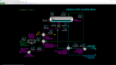
Process Description
The objective of the Crude Oil Desalter process is to remove salt compounds contained in wet crude oil and to separate most of the water contained in the wet crude oil. A desalted crude oil, low in water concentration and salt content is produced. This makes the desalted crude oil more suitable for refinery processing because it is less likely to cause plugging and fouling of equipment from solid salts agglomerating at some point in the process. The crude oil is also more valuable due to its lower water concentration. The process also tends to remove most of any suspended solids that may be contained in the wet crude oil.
The Crude Oil Desalter simulator represents a standalone unit that is typically found in crude oil production facilities. However, the processing scheme and controls are very much the same as desalters found in the preheat trains of crude distillation units found in oil refineries. Quite often, two stages of desalting may be employed in crude oil processes for maximum removal of salt and water. In all of these variants of desalter designs, the principles of operation are identical to those presented in the Crude Oil Desalter simulator.
The Crude Oil Desalter process takes wet crude oil pumped by P-401A/B from storage and preheats the crude to the ideal separation temperature In E-401 and E-402 before entering the Desalter D-401. Clean makeup desalter water is pumped by P-402A/B into the warmed wet crude oil line upstream of the mixing valve HV-401. The mixing valve ensures intimate mixing of the crude oil and water before being distributed in the Desalter vessel. Most of the salt contained in the water portion of the crude oil will dissolve in the desalter water as a result of this mixing. A water-to-oil treat ratio of 5% by volume is used in the design operation. The mixed oil and water is evenly distributed into D-401 using specially engineered distributors.
The water portion of the wet crude will often exist as a stable emulsion, depending on the specific composition of the crude oil. The addition of desalter water will not usually be able to completely break this emulsion. The following features of the Crude Oil Desalter process are used to break the emulsion and separate the water and crude oil phases:
- Long settling time due to the large volume of the Desalter vessel to promote maximum phase separation of water and crude oil
- Electrical grid with high voltage applied across the grids to promote coalescence of the smaller water droplets into large ones which will settle out of the oil phase more quickly
- Crude oil preheater to maintain the optimal density difference between the oil and water phases (crude oil density changes more with temperature than does water)
- Demulsifier injection facilities to promote breakage of the emulsion using a chemical agent
Coalesced water from the crude oil and the injected desalter water is collected in the bottom of Desalter D-401. This water is briny (contains salts) and is used to preheat the fresh desalter water in E-403 before being sent to battery limits. Desalted crude oil is drawn from the top of D-401 and is used to preheat wet crude in E-401 before final cooling in E-404 prior to being sent to storage.
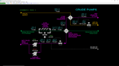
Crude Oil Pumps & Preheat
Wet crude oil is pumped from storage by Crude Pumps P-401A/B which are centrifugal, motor-driven pumps. The design flow of wet crude oil is 35.0 MBPD5.57 KM3/D. Wet crude oil flows to Crude Feed/Desalted Crude Oil Exchanger E-401, which is a shell and tube heat exchanger that partially warms the feed using warm desalted crude oil taken from Desalter D-401.
The warm wet crude oil is further heated in Crude Preheater E-402 which uses hot oil from battery limits to heat the crude oil. The normal outlet temperature of the crude oil from E-402 is 300 DEG F149 DEG C. Cooled hot oil is returned to battery limits. The crude oil from E-402 continues on to the Desalter D-401.
Cooled desalted crude oil from E-401 undergoes final cooling in Desalted Crude Cooler E-404 which is an air cooler with a motor-driven fan to move ambient air through the cooler. The desalted crude oil from E-404 is sent to storage at battery limits.
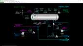
Desalter
Warm wet crude oil from E-402 flows through the mixing valve HV-401 before entering the Desalter D-401. A check valve prevents back-flow of desalting water into the wet crude line and equipment. HV-401 is a conventional control valve with sufficient pressure drop to ensure good mixing of desalter water with the wet crude oil. The normal pressure drop across HV-401 is 7.9 PSI0.54 BAR. Most of the salts contained in the wet crude oil are dissolved into the injected desalter water as a consequence of the mixing taking place in HV-401.
Desalter water from Desalter Feed Water Pumps P-402A/B is injected into the wet crude oil line just upstream of HV-401. A check valve prevents back-flow of crude oil into the desalter water line and equipment. The design flow rate of desalter water is 51.0 GPM11.73 M3/H. The design ratio of desalter water flow to wet crude oil flow is 5% on a volume basis.
The Desalter operates at 50 PSIG3.45 BARG in order to keep any of the lighter crude oil components from vaporizing as they are heated in the preheat exchangers of the Crude Oil Desalter.
In case of emulsions that are very hard to break, a demulsifier injection system is provided. Demulsifier is taken from storage by Demulsifier Pump P-406 which is a motor-driven centrifugal pump. Demulsifier is injected into the wet crude oil line upstream of HV-401. A check valve prevents back-flow of crude oil and water into the demulsifier line and equipment. Normally, there is no demulsifier injected into the wet crude oil. The demulsifier system is designed to provide up to 0.5 volume % ratio of injected demulsifier to wet crude oil if needed.
The Desalter D-401 is a large vessel which provides sufficient residence time for the oil and water phases to separate and for the water droplets to coalesce and settle into the bottom of D-401. The residence time of oil in the Desalter is about 12 minutes in the simulator. Real units may have longer residence times depending on their design. The oil/water mixture from HV-401 is distributed into the middle-upper section of the Desalter - where the electrified grids are situated - and evenly along the length of the Desalter. The distributors are designed to minimize oil/water recirculation and backmixing which helps the water droplets coalesce faster. Faster coalescence means the Desalter vessel size is minimized.
As mentioned above, the Desalter is also outfitted with a set of two, parallel electrified grids that are situated above the maximum indicated level of water in the dry oil phase. These grids are oriented horizontally throughout the Desalter vessel. The top and bottom grids (electrodes) are separated by 15 inches30 cm. The oil water mixture from the distributors enters just below the grids. A rectified (one-way current) voltage of 15,000 volts (15 KV) is applied to the grids, which act as electrodes in generating an electric field between them. The electric field causes small water droplets to align vertically due to their polarity (water molecules have a positively charged end and a negatively charge end). This alignment promotes the attraction of adjacent water droplets to each other better than the random alignment which occurs without the presence of an electric field.
When oil/water emulsions are difficult to break, demulsifier can be added. A demulsifier is a special chemical that will help break the water droplets of the emulsion by lowering the surface tension at the droplets’ surfaces. As a result, the droplets join more easily with other water droplets and become larger drops. The larger water drops will separate out and fall more easily to the bottom of the Desalter than the fine water droplets of an emulsion.
The Desalter also includes a Mud Wash system. This system circulates briny water around the base of the Desalter vessel D-401 to loosen any sediment that has settled from the wet crude feed. Mud Wash Pump P-404 circulates the briny water through the Mud Wash piping. Any loosened sediment will be taken out with the briny water. Normally, the Mud Wash Pump P-404 is not in service. A good practice is to circulate water through the system every 15 to 30 minutes for a minute or two.
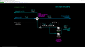
Water Pumps
Makeup desalter water from tankage is pumped by Desalter Feed Water Pumps P-402A/B which are electric motor-driven centrifugal pumps. The feed water is warm and is preheated in Desalter Water/Briny Water Exchanger E-403. The water is preheated to 274 DEG F135 DEG C in E-403 and continues on to the Mixing Valve HV-401 of the Desalter D-401. Hot briny water from Desalter D-401 enters E-401 at 297 DEG F147 DEG C and is cooled to 246 DEG F119 DEG C and is sent to a sour water stripper at battery limits. Briny water can contain significant amounts of sediment from the Desalter and, therefore, passes through the tubes of E-403 to minimize the possibility of sediment accumulation in the heat exchanger compared with sending the briny water through the shell side.
IInstrumentation
Crude Pumps
The motors of Crude Pumps P-401A/B are controlled by hand switches HS-401A and HS-401B, respectively. Normally, P-401A is operating and P-401B is off. The wet crude oil temperature is indicated on TI-401 and the basic sediment and water (BS&W) content of the wet crude is indicated on AI-401 as weight percent. The flow of wet crude oil is controlled by FIC-401 which adjusts the position of control valve FV-401. The process value (PV) of FIC-401 is sent to makeup water ratio controller RIC-402 (see Water Pumps section below).
The wet crude oil outlet temperature of Crude Feed/Desalted Crude Exchanger E-401 is indicated on TI-402. The temperature of the desalted crude oil leaving E-401 is indicated on TI-405 and the BS&W content of the desalted crude oil is indicated on AI-405.
The wet crude oil outlet temperature of Crude Preheater E-402 is controlled by TIC-403 which adjusts the setpoint of hot oil flow controller FIC-408. FIC-408 controls the flow of hot oil to E-402 by adjusting the position of control valve FV-408. The temperature of makeup hot oil to E-402 is indicated on TI-408 and the temperature of the hot oil leaving E-402 is indicated on TI-409.
The motor of Desalted Crude Cooler E-404 is controlled by hand switch HS-405. The temperature of cooled crude from E-404 is indicated on TI-406.
Desalter
The position of Mixing Valve HV-401 is controlled by hand controller HIC-401. The pressure drop across HV-401 is indicated on PDI-401.
The motor of Demulsifier Pump P-406 is controlled by hand switch HS-406. Normally, P-406 is off. The flow rate of demulsifier to D-401 is controlled by FIC—406 which adjusts the position of control valve FV-406.
The power to the grids of Desalter D-401 is controlled by hand switch HS-403 which is tied in to interlock I-401 (see Interlocks below). If I-401 trips, it will lock HS-403 in the OFF position until all trip inputs are clear. After a trip, the power to the grids must be manually restarted using HS-403. The voltage across the grids of D-401 is indicated on EI-401. The nominal power input to the system is normal 15.0 kV but E-401 will indicate somewhat less depending on the current draw by the grids. II-401 indicates the current draw of the grids. IHH-401 is an independent sensor of the current and is an input to Interlock I-401.
LIC-402 controls the water-oil interface level of Desalter D-401 by adjusting the setpoint of briny water flow controller FIC-405 which controls the briny water flow rate by adjusting the position of control valve FV-405. LHH-401 is an independent indication of the water-oil interface level for use in the Desalter interlock I-401.
The pressure of the Desalter D-401 is controlled by PIC-402 which adjusts the position of control valve PV-402. The temperature of desalted crude oil leaving the top of D-401 is indicated on TI-404 and the flow of desalted crude oil through PV-402 is indicated on FI-403.
The temperature of the briny water leaving the Desalter is indicated on TI-413.
The motor of the Mud Wash Pump P-404 is controlled by hand switch HS-404. Normally P-404 is not in operation. The position of mud wash control valve HV-404 is controlled by HIC-404. The flow rate of circulating water through the Mud Wash circuit is indicated on FI-404.
Water Pumps
The motors of Desalter Feed Water Pumps P-402A/B are controlled by hand switches HS-402A and HS-402B, respectively. The temperature of the supply of desalter water is indicated on TI-411. The flow rate of desalter water to Desalter Water/Briny Water Exchanger E-403 is controlled by FIC-402 which adjusts the position of control valve FV-402. The volumetric ratio of desalter water to wet crude is calculated by dividing the PV of FIC-402 by the PV of the crude feed flow controller FIC-401. This ratio is controlled by ratio controller RIC-402 which adjusts the setpoint of desalter water flow controller FIC-402. This ratio is normally 5.0%.
The temperature of desalter feed water leaving E-403 is indicated on TI-412. The temperature of briny water leaving E-403 is indicated on TI-414.